Tip: Simple Sander or Polisher

;

Here’s a very easy way to make a quick and simple tool that you can use for sanding or polishing. This tool can be made in literally 30 seconds; all you need is a piece of music wire!

;

So to start grab a piece of wire (I prefer music wire because it is strong, yet flexible) and also get a pair of pliers. All you do is about 1″ or so from the end of the wire, bend a 90 degree angle with the pliers. Then continue bending until you fold the wire back onto itself. That’s it! You’re ready to add sandpaper for sanding or a papertowel for polishing.

;

I normally use sandpaper with this not so much for sanding wood (although you could use it for that) but for honing cylinders or the like. What I like about this tool is I can use a piece of 220 grit sandpaper and then when I’m ready I can quickly and easily switch to 400 grit sandpaper and then onto 600 grit sandpaper. To put on a piece of sand paper, all you do is cut a strip of sandpaper about 1-1/2″ wide (or however wide you like) and about 4″ or so long. Then slide one of the ends of paper into the pens of the wire and roll up the sandpaper. Now to use it, stick the wire into a drill or into a Dremel and you’re ready to go!

For polishing it’s the same thing except with a paper towel. Cut a strip of paper towel and stick it in the wire. Now I personally like to cut my paper towel strip about 3″ wide and fold it over on itself to make it a little thicker, but you can do whatever floats your boat. Then roll it up and put some polish on it. The polishing compound will hold the paper towel together as a tight roll which is nice.

Like I said before, it’s that easy!

;


Posted in Tips and Tricks, Tools Tagged back, backroom, buff, buffer, corded, cordless, desk, disk, drill, easy, flap, flap-wheel, flapwheel, homemade, inside, or, paper, polish, polisher, polishing, quick, room, sand, sander, sandpaper, simple, wheel, wire, work, workdesk

Testors McCoy .049 Update

It’s been close to eight months since my first blog post which was the cleaning and restoration of my Testors McCoy .049 engine. If you follow my Facebook page you probably know that I got some fuel for this engine Thursday I think it was. The fuel I ordered was SIG Champion 25 which has 25% nitro and 20% oil (1/2 castor and 1/2 Klotz synthetic). I tried to start my engine the first time Friday night.

As I was flipping the propeller with a chicken stick, the chicken stick went and hit the needle valve which bent it sharply. As I carefully tried to bend it back enough to be usable, it sheared in two with it being fully screwed into the engine. I had to file a slot into the end of the needle and use a screwdriver to back it out. I then soldered it to some brass and went back to starting the engine.

I flipped the engine for a long time with no reward; the engine wouldn’t start. So I did the only thing I could do, I grabbed my electric starter. I used the starter and on my third try, I got the engine running. It ran for about 2 seconds and then quit. I didn’t get it started again that night.

Sunday afternoon I had some time to try again. I first used my chicken stick for about 45minutes. This time I got some really good ‘pops’ with the occasional quick sputtering of the engine lasting only a second or so. Again I grabbed my electric starter. I got the engine running again using the E-Starter. It ran for probably 5 seconds and then died. I tried for a while longer until my glow plug was dead.

Yesterday morning was the last time I tried to get the engine running. I used the chicken stick for about 20 minutes with promising results. Although I never actually got it running, it would turn over on its own about a dozen revolutions and then stop. It did this very often. Maybe every other flip or so. While trying to start it yesterday I had to continually stop, plug in glow starter to charge, and come back in 15minutes or so to try again. My glow starter is really old and doesn’t hold a charge that good so I’m always having to deal with it dying. So when it died and I plugged it in to charge, I went to find a better way to make my glow plug glow; something that would never die and will always be constant – a power supply.

I started out with small power supplies. I would rig then to my 1/2A glow clip and attach the clip to just the glow plug so I could see if it would make it glow or not. I would very quickly touch the center of the pole of the glow plug with my clip and then very quickly remove it. I did this to see if it would be too much for the glow plug to handle. If it didn’t shine red hot instantly I repeated the process multiple times but each time leaving it connected slightly bit longer to see if it worked. I did this to two power supplies (one with more output than the other) and neither one would even make it glow a little, so I got my third sized power supply. It was just about half an amp more output than the biggest power supply I had already tried. I hooked it up and began my process. I connected the clip to the glow head and extremely quickly (probably less than 1/10 of a second) touch the center pole of the glow head and removed it. POOF! The glow plug’s nichrome wire instantly vaporized in a flash of red-orange flame. I instantly knew I was screwed 🙁

I knew I couldn’t repair it. I looked online to see if I could drill and tap the head for a regular glow plug but everywhere I read says that it messes up the size of the combustion chamber and it causes the engine to not run well. So I’m really upset. I’m mainly mad at myself, but also upset that I screwed up something that’s pretty hard to find.

I would order a new head off of eBay, but I don’t have the money right now because I have spent it on two new Cox .049 Sure Starts from someone off of RCGroups. So those should fill my need for a 1/2a engine. I will also be putting one on my first balsa scratchbuild that I plan to start sometime after Christmas. . .

Posted in .049 Restoration Tagged broke, burnt, fail, glow, head, mccoy, plug, testor

DIY 1/2A Engine Glow Clip

As you may know I have a small 1/2A engine – a Testor’s McCoy .049. I have been wanting to start it ever since I got it back in the spring. Well yesterday I ordered some fuel for it! I ordered a quart of Sig Champion 25 which has 25%nitro and 20% oil (1/2 castor and 1/2 synthetic). I planned to start the engine when the fuel arrives, but then I realized I don’t have a glow clip for it! I have a glow starter for a larger engine. The kind that twist locks on, but that won’t work with this small engine so I investigated where to buy one at. I came across this one  from Amazon.com for about $12. Well obviously I didn’t buy it, or there would be no blog post today. So, I’ll go ahead and show you what I did so you can make one yourself.


The first thing I did was go watch some YouTube videos of people starting their small Cox engines to see how the glow clip attaches and whatnot. After watching some videos,  I realized that it is just a spring clamp with metal pieces that are wired to a battery. So I went and found a clothespin, a piece of brass (leftover from my boat project), and some wire. My plan is to have a fork on the bottom of the clothespin that will slide onto the engine, and  piece of metal that will mount to the top of the clothespin and will touch the center post of the glow plug. So I began working on the fork first. I sketched it out on the brass and cut it out using the combination of a hand nibbler and tin snips. The nibbler was used for the center of the fork part, the tin snips were used for the outer shape. I then used multiple different files to make it nice and smooth. I then cut out a strip of brass that acts as the top piece of the clamp.

I then warmed up my soldering iron and began to solder. I soldered an 18″ wire lead to each brass piece. I still don’t know what I’m going to do with the other end of the wire. Right now I just stripped it. I don’t know if I’ll put alligator clips on, or maybe some type of other plug.  This  Anyway, once I soldered the wires on I tried it on my engine.

I works just like I hoped it would’ve. It slides right onto the engine, and then clamps on. If you see in the picture the top piece of the clip is got a bend in it. This is so it stays on the center post of the glow plug better. I made this bend by using a center punch and repeatedly using it until it was bent in the way I wanted. I tried it out with a battery and it makes good connection with the glow plug and makes it glow red hot. I think this free version works just as good as the $12 version.


Posted in Tools Tagged .010, .020, .049, .0498, 061, 1/2, 12a, 15, a, airplane, battery, Clamp, clip, Coy, d, DuBro, engine, fly, glo, glow, hot, i, Ignite, Igniter, Mc, mccoy, plug, RC, start, Sullivan, testor, testors, y 2 Comments

OS MAX .15 FP Cleaning

A little over a week ago I went to a flea market type business in my area where I bought an RC airplane that had a nitro engine on it. The plane is balsa and the engine is a OS Max .15 FP. I have been flying electric airplanes for close to two years now, but never one powered by an internal combustion engine. Glow engines are pretty much new to me so I’ve learned quite a bit since I’ve bought the engine. My plan is to start the engine in the next few days so the other day I cleaned the engine to get it ready for starting.


I don’t know the history of this engine, but after some research I’m pretty sure the engine was manufactured sometime in the late ’80s. Although the outside of the engine was pretty grimy and covered in old fuel, I don’t believe it has ever been run. The reason I believe this is because when I took off the back plate of the engine there were no signs of fuel. No gummed up Castor oil, no residue from any liquid, nothing. Also after talking with one of the owners of the local hobby shop, he also believes it had never been run because if it had it would not be easy to turn the prop over because it would be gummed up and whatnot. This was not the case, the prop turned over just fine. With this information I feel that I got a pretty great deal: $20 for a ready to fly (minus receiver) balsa airplane and a brand new engine!


Anyway, the way that I cleaned it was by using a toothbrush and Isopropyl alcohol. I took the advice of a few RCgroups members and plugged the fuel inlet port, the carburetor air intake valve, and both muffler exhaust ports so the alcohol wouldn’t get into the engine. I scrubbed the outside of the engine with the toothbrush and got in all of the nooks and crannies and eventually got all the crud off the engine. When I finished up cleaning the outside of the engine the engine looked awesome! The engine went from old and dirty looking to shiny and new in just a few minutes!  After talking with some RCgroups members, we decided that it was unnecessary to completely dismantle the engine and do a full cleaning. My best bet, they said, is to just try and start it so that is just what I’ll do!


When I get the engine running I’ll take some video and will upload it to my Facebook page. So, if you want to make sure you see the video you may want to go ‘like’ my Facebook page *wink*


Posted in Remote Control Tagged ., 1, 15, 5, airplane, back, backroom, clean, cleaner, cleaning, cool, engine, F, fly, FP, fuel, gas, glow, Max, motor, nitro, O, old, OS, P, RC, run, S, start, starter, starting, tune, tuning, work, workdesk

Broken Light Fixture

This past week I discovered that the light fixture in our bathroom was coming apart at the seams. Since it appeared that it could completely break and fall on someone, I decided to fix it.

After getting the fixture down I began to work on it. There were two places where the glass frames were coming apart. I realized that I would have to cut off some of the existing glue to fix the fixture, so I grabbed my Xacto knife and began to do so. As I started to try and remove some of the glue, I noticed something odd: the glue wasn’t glue at all. It was lead. I found this to be pretty strange. I would’ve never guessed that’ve fixture would be held together by lead! I know that they use lead to fixate glass in stained glass windows, but this light fixture has little metal frames around each pane of glass so the lead is not necessary. Either way, I began to cut away at the lead.

Once I removed enough lead I began to close up the cracks. I pushed the two pieces of glass that were seperating together and used some tape to hold them there. I then did the same thing for the other crack that was forming. At this point I had the light fixture they way I wanted it, it just need to be glued up.

I decided to use 30minute to hold the fixture together, but when I was finished with the glue up I didn’t want spicy to be all over the glass. To fix this potential problem I took masking tape and covered every pane of glass on the inside of the fixture. Then using an xacto knife I cut around each pane of glass and pulled up the tape to expose just the metal frames that surround each glass pane. Knowing how messy epoxy can be, I went ahead and covered the outside o the fixture as well. To do this I just used some newspaper paper and taped it to the outside. Now I was ready for gluing.

I slipped on some latex gloves, mixed up my 30minute epoxy, and began to apply it to the inside of the light fixture. I put good amounts of glue on the cracks that were in the fixture. So I wouldn’t have to fix the fixture again in a few years, I went ahead and applied epoxy to every metal frame inside the fixture. I then left the epoxy alone to cure.

The next step was my favorite: removing all of the tape! I removed all of the masking tape which exposed perfect, epoxy free, panes of glass. This made me happy. I was then ready to go put the light fixture back in its home in the bathroom.


Posted in Miscellaneous Tagged back, backroom, Bathroom, build, c, Epoxy, Fix, Fixture, glue, Hang, home, homemade, i, light, made, room, work, workdesk, y

JR Radio to USB – FAIL

This week’s post is different than all of my other blog posts. Normally I show you something that I have made that worked like I had hoped. . . .well not this week. I planned on showing you what I had been working on at the end of last week and over the weekend but it ended up not working out at all. I am still going to show you what I did, just keep in mind that it is a complete fail – it just doesn’t work.

I fly RC planes and sometimes I will use a simulator to practice. I have been wanting to learn how to do 3D stunts, so recently I have been using the simulator more than before. My current setup is to use a cheap Esky 4ch radio with a USB cable to use FMS (Flying Model Simulator). My only problem with that setup is I don’t fly my planes with the el cheapo Esky radio, I use my nice JR 8103. I looked into it and I can in fact buy a cable that goes from my JR radio to the computer. When I saw the cable online, it looked identical to the current cable I was using except for the one online (for the JR) had a mono headphone plug on the end and not an Esky connector. So I decided to modify my current cable to make it work with my JR.

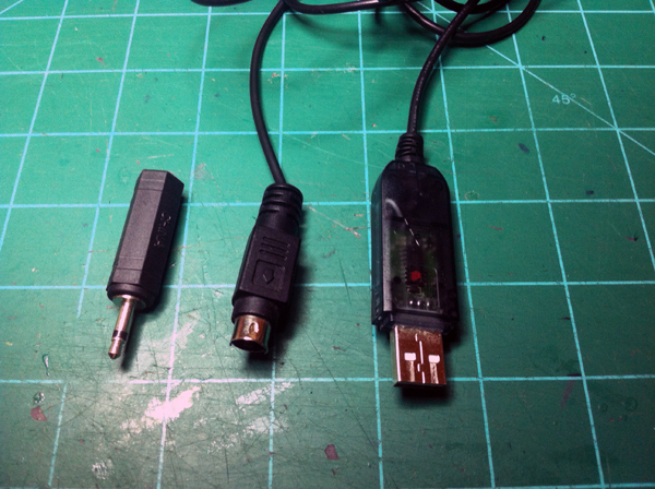
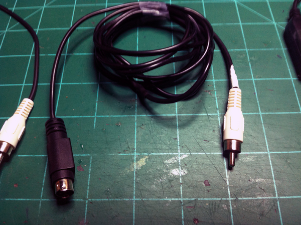
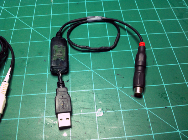
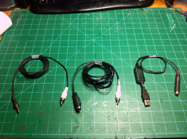
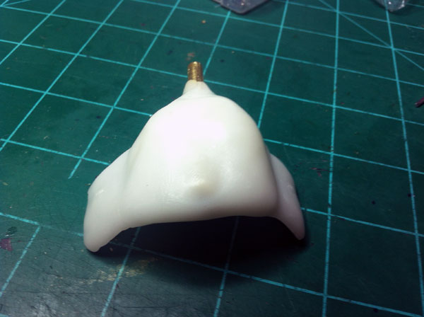
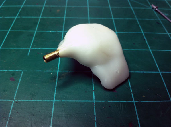
I went and scrounged up parts to make the new cable. I didn’t have a straight up 1/8″ male mono plug, but I did have a 1/3″ plug to 1/8″ lug adapter so I used that. For this cable I didn’t want to completely get rid of my Esky plug because what if I was outside flying (with my JR radio) and my little brother wanted to use the sim? He wouldn’t be able to. So I decided to make the plugs switchable to where I could either use my JR plug or the Esky plug. After cutting the USB cable and seeing that there were only two wires going from the transmitter to the computer I decided to use an RCA plug as a quick disconnect. I soldered onto the USB end of the cable a female RCA plug and to the Esky plug end of the cable I soldered on a male RCA plug. This way it is a very easy, simple connection. After I did this I began to work on the JR plug . . .

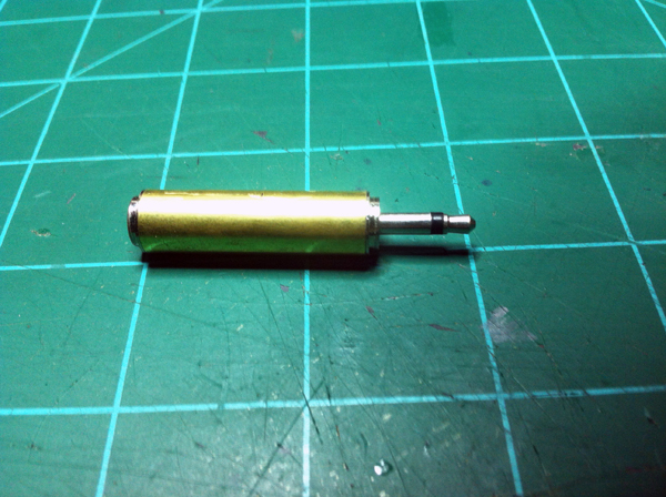
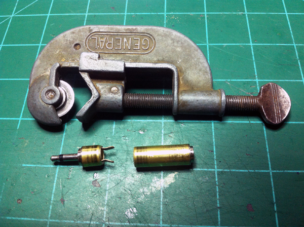
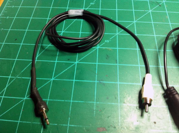
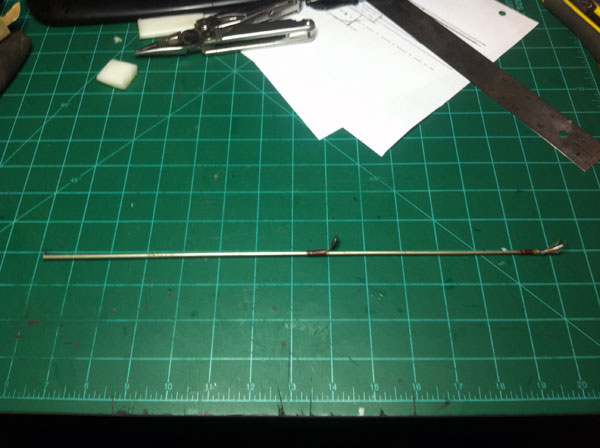
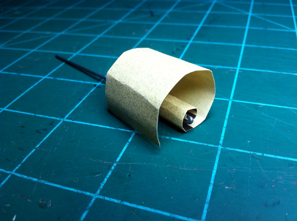
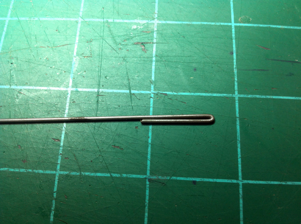
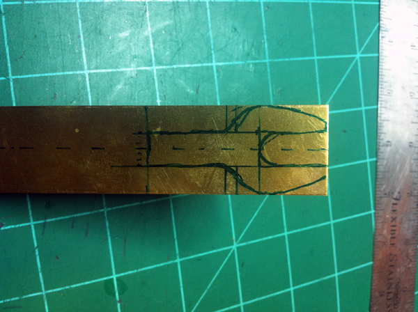
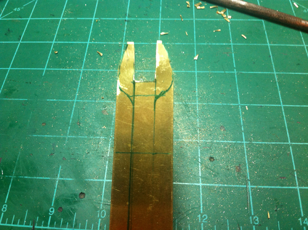
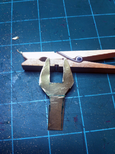
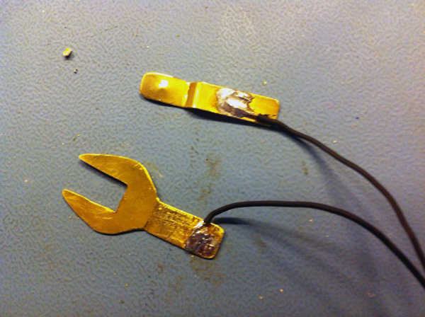
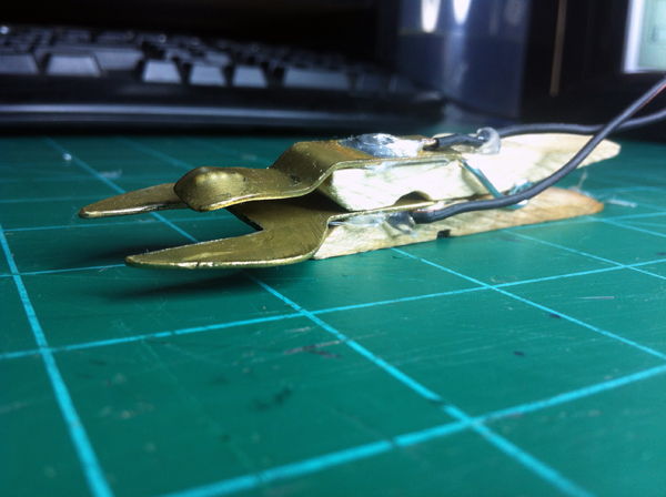
I took my 1/4″ to 1/8″ mono plug adapter and cut off the plastic housing which exposed a metal tube. I couldn’t access the center pole of the 1/8″ plug that I needed to solder to, so I took my mini pipe cutter and cut the metal tube near the 1/8″ plug side. At this point I found online the JR trainer port pinout and the Esky trainer port pinout and using this information I figured out what wires need to go to where on my new JR cable. I went and got me an RCA cable that had a male connector on one end and decided to use this for the JR sim cable I was making. I then soldered onto the end of this cable the 1/8″ mono plug and heat shrinked it all up.

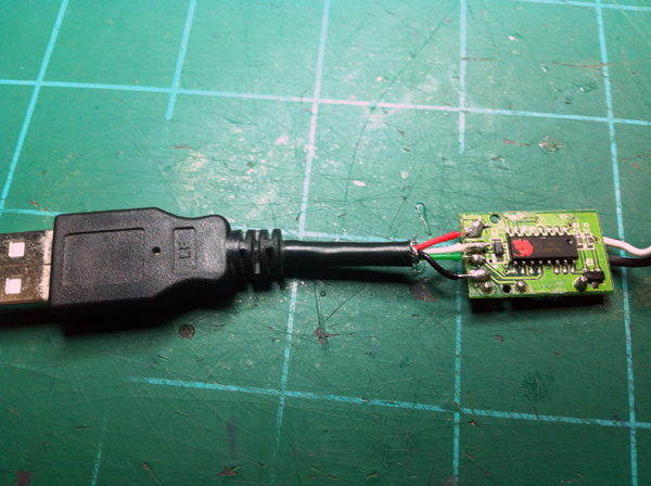
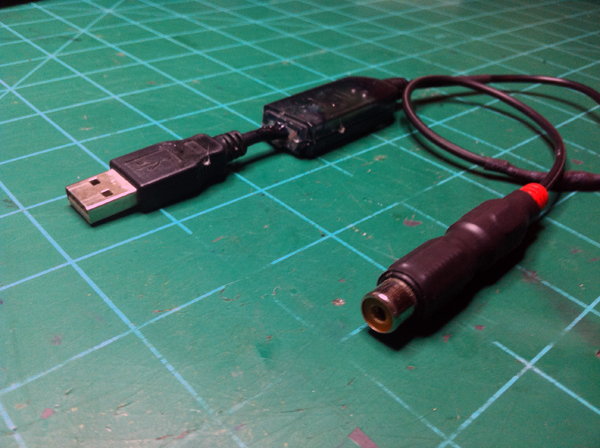
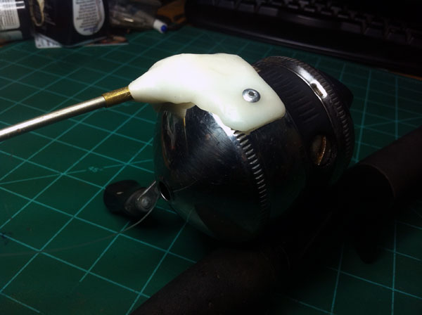
At this point my JR sim cable was finished, but I couldn’t test it yet because my 3 year old Esky USB sim cable had gone finicky at the USB plug solder joints. Ugh. So I then had to fix that. I found a USB cable that I didn’t need anymore and cut off the male USB plug. I then opened up the USB dongle that was on the end of the Esky simulator cable and de-soldered that broken USB plug. After finding a USB’s pinout online, I soldered the new USB plug onto the Esky sim cable. Then hot glued the new USB plug’s cable to the plastic housing as a stress relief and then closed up the plastic housing.

To make sure everything was working fine still and that I soldered the USB plug on correctly, I hooked up my sim cable with the Esky plug on it and fired up the simulator. It worked like before (except it wasn’t finicky 😀 ). When everything checked out fine, I closed down the simulator, put the JR plug on, plugged in my JR radio, and then went back to the simulator. Nothing. Didn’t work. I then went to my computer’s control panel to calibrate it in the gamer control’s settings and Microsoft didn’t even recognized it. So I then began trouble shooting. I rechecked my solder joints, checked continuity on the wires, made sure my transmitter was in the right mode with the right settigns, as a test I switched wires on the plug (Ground became data and data became ground), googled, asked on RCgroups, . . .  Still nothing. It was a big let down because I had spend a couple of hours on it and even more time troubleshooting.

I thought I’d go ahead and share what I did do, even if it didn’t work out. I guess I will now have to order me a cable *wipes tear* 😛
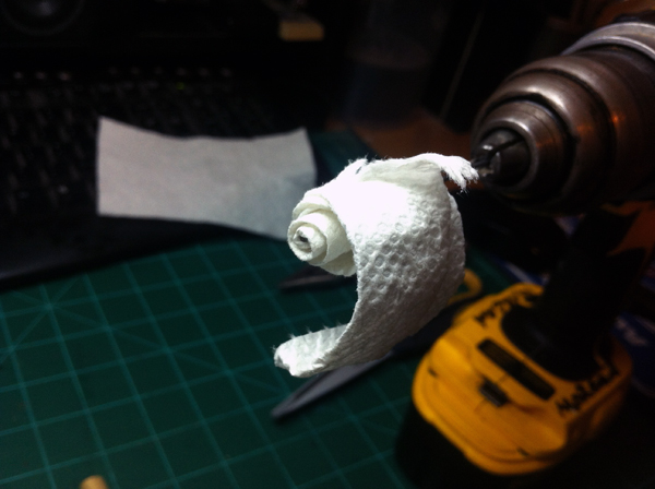
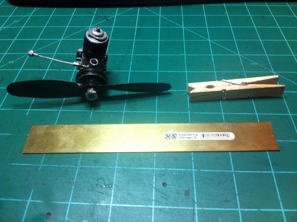
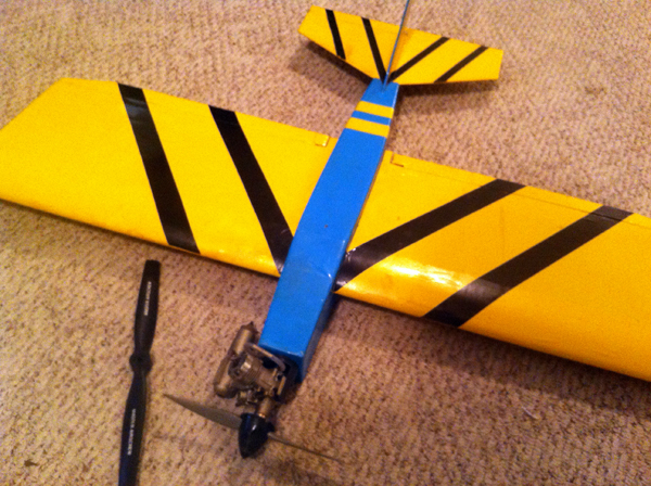
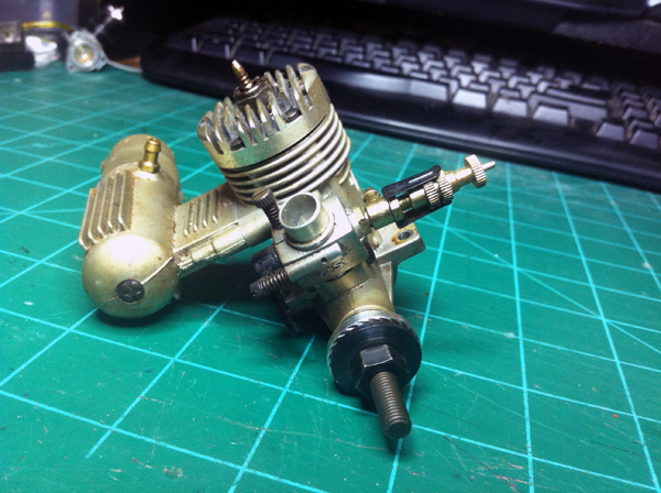
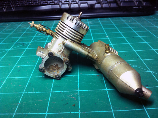
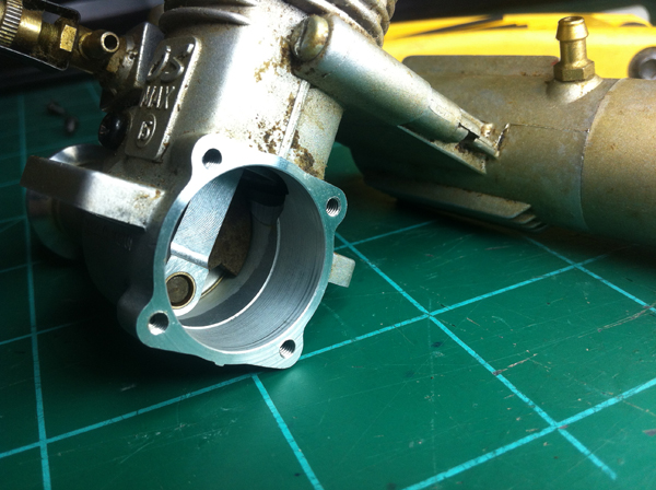
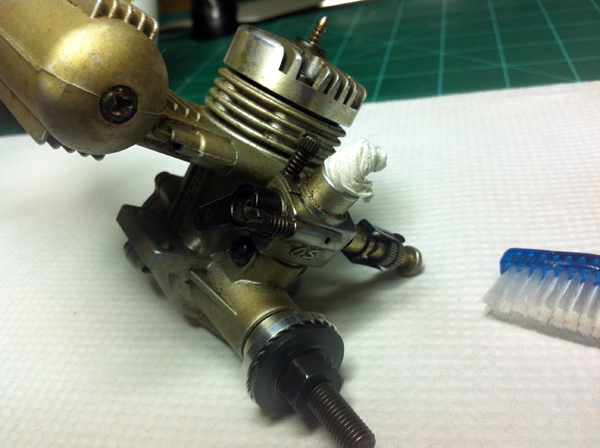
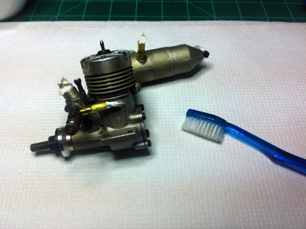
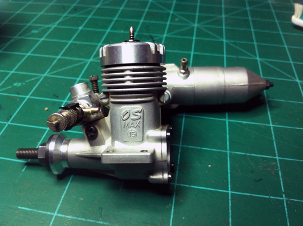
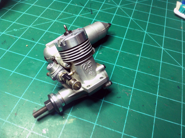
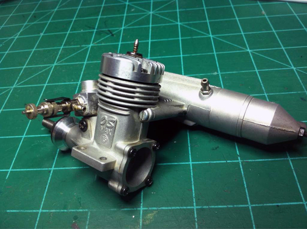


Posted in Miscellaneous, Remote Control Tagged 8103, back, backroom, build, c, cable, computer, control, d, disconnect, diy, esky, fly, home, homemade, i, JR, made, pinout, plane, plug, quick, r, radio, RC, rca, remote, room, sim, simulator, trainer, transmitter, tx, usb, work, workdesk, y

Tip: X-Acto Blade Disposal


This is something that I made about a year ago and I have used it just about everyday since. I go through quite a bit of exacto knife blades but throwing them away used to be a problem. I can’t throw them straight into the garbage because first of all it would/could cut the garbage bag and secondly because if I, or someone else, was trying to find something in the garbage they could slice their hand with the used exacto blades in there. To fix this problem I just used a film canister as an exacto blade trash can.

All I did was take a film canister and superglue the lid to it so it should never come off. Then I took my exacto knife and cut a slice in the lid. This is the slot that I stick the old blades in. I then wrote on the canister “Do not open” and stuff like that so no one accidentally opens and spills them all.

That is it. Extremely simple, but much safer than just throwing the blades right into the trash. I also put snap off blade pieces in the canister.

Posted in Tips and Tricks, Tools Tagged acto, away, back, backroom, blade, build, c, canister, control, d, dispenser, disposal, dispose, diy, e, exacto, exactoxacto, film, home, homemade, i, made, r, RC, recycle, remote, room, safe, safely, safety, throw, tip, work, workdesk, x, x-acto, xacto, y 1 Comment

JT Extended Ear Coverage


I recently purchased a JT Flex 8 Full Coverage paintball mask. So far I like everything about the mask . . . . except for one thing: the lack of ear protection. I don’t quite understand it really. The company took their time to create a real nice mask with a great lens, but they skimped on the ear protection! Well I wasn’t going to play paintball with my lower ears exposed so I added on  ear protector extensions.

The criteria that the ear protectors had to meet for me were:

—– It had to add sufficient coverage to my ears and upper neck area

—– It couldn’t irritate me when I had my mask on. That means it can’t be in my way or rub my neck when I look around.

—–The way it attached could not alter the mask in any way. What I mean by this is I didn’t want to drill holes in the mask or glue it to the mask because if I ever decide to sell the mask I don’t want to have to worry about not getting full value because of holes or glue.


So this is a very (very) simple ‘mod’. All I did was cut out some 1/8″ plastic into an ellipse-ish type shape and drill some holes in it. I drilled the holes in the area where the mask vents are located. I then sanded the plastic’s edge smooth. To attach the extensions I ran a mini zip tie through one of the holes in the plastic piece, then through the mask and around one of the vent bars, back through another hole in the plastic, and then tightened it up. This way if I ever want to remove it, I just cut the zip tie.


My only problem (and it’s not really even a big deal) with the extensions are that it makes it a little more trickier to put the mask on. Other than that I have no problems so far. I do plan to spray paint them black so they don’t stand out as much. I used this mask over the weekend during a game and it worked really well. Although I wasn’t shot in the ear area, I’m glad I had the extra protection just in case.


Posted in Outdoors, Weapons Tagged 8, action, back, backroom, ball, build, c, control, cover, coverage, d, diy, ear, extend, extended, flex, full, goggle, goggles, home, homemade, i, J, JT, JT flex, KEE, lens, long, made, mask, mod, modification, neck, paint, paintball, pro, proflex, proteck, protect, protection, room, safety, spectra, spektra, sports, T, thermal, tie, war, work, workdesk, y, zip

iPhone Life Vest

As I stated in my last blog post, my family has been talking about going canoeing again. For safety reasons I plan on keeping my iPhone with me in the boat. Although I have a Lifeproof case on my phone that keeps it waterproof, if our canoe ward to flip over, my iPhone would sink to the bottom of the river! The last thing I want to do is be searching for my sunken phone, so I built a life vest for my iPhone.

The life vest is made from a single piece of 2-inch foam insulation. To build it the first thing I did was trace the outline of my phone onto the foam. After that, I drew a line on every side of the phone outline 1/2″ from the outline. This perimeter will be the size of the life vest. At this point I cut out the shape of the life vest using a box cutter. The rough dimensions of this foam rectangle are ~6″ x ~3.5″.  I then began to hollow out the foam so my phone can slide in.

On one of the smaller edges of the foam I drew a rectangle the width and thickness of my phone about 1/2″ away from what will be the front face of my life vest. Then after sharpening the largest brass tube I had, I began to hollow out the foam. I did this by starting on the edge that I had the rectangle which was the width by the thickness of my phone drew. I then started plunging the brass tube perpendicular to the edge I was working on inside of this rectangle. As I pulled out the brass tube, the brass tube brought along with it a long plug of foam. I had a mark on the brass tube so I would know how deep into the foam I should shove it. After working on hollowing out the foam for a good 15 minutes, I was finally finished. At this point I could slide my iPhone into the chunk of foam and take it out, the only problem was I couldn’t see the screen!

After doing some measurements of my iPhone, I found out where the screen of the phone would be at when the phone was inside the foam. I then cut this section of foam out, plus a little more so I would be able to press the ‘home’ button when the phone is in the foam. At this point I was able to slide my phone into the chunk of foam and press the ‘home’ button. When I got to this point the foam was able to function as a usable life vest, but it looked horrible! So I made it look a bit nicer.

To make it look good, I took a box knife and angle the four edges of the back face of the foam. After that I used sandpaper to make all of the edges nice and round. To me, this looks a whole lot better than a perfect rectangle with square edges.


Posted in Miscellaneous, Outdoors Tagged 2, apple, back, backroom, Boat, boating, build, c, canoe, cell, cellphone, control, d, diy, fish, fishing, float, foam, home, homemade, i, inch, iPhone, ipod, kayak, lake, life, lifeproo, lifeproof, lifevest, made, paddle, phone, preserver, proof, river, room, sank, sink, stream, sunk, swim, touch, vest, water, work, workdesk, y

Mini Fishing Rod

My family and I have been talking about going canoeing sometime soon. We went canoeing for the first time about two years ago and had a great time, but after it was over there was one thing we all wish we had brought on the boat ride: a fishing pole! All we wanted was a small fishing rod so we could just have a line in the water as we floated along the river. It’s not for serious fishing, just for fun. So now that we have been talking about going again, I have built a couple of small fishing rods to bring with us.

Over the summer I saw at a yardsale a small fishing rod called a pocket fisherman. It was really cool, and it was only about 14 inches in length. At the time, I had no need for a pocket fisherman, so I didn’t buy it. The two mini fishing rods I have built are inspired by the pocket fisherman.

To begin this project I dug out my old fishing reel and a few broken fishing rod pieces. The reel I am using is a Zebco 33. To build the mini fishing rod I took a piece of fishing rod that had the handle on it and cut the fiberglass tube right pass the end of the handle. I cut the fiberglass tube because for this mini fishing rod I only will be using the very end of a fishing rod, not the large diameter part. To cut the fiberglass rod I unscrewed the nut that holds the reel on, wrapped the fiberglass tube where I was going to cut with masking tape, and began to cut with a coping saw. I moved the coping saw fast, but I used very little downward pressure during the cut. This yielded a very smooth edge on the fiberglass. After putting the scrap piece of fiberglass tube away for future projects, I began to work in the reel.

My plan is to mount the end of a fishing rod to the reel with the eyelets facing down. So, to begin I cut a piece of fishing rod that had the just the last two eyelets on it the same way I cut the fiberglass tube earlier. I then stuck this cut piece of fiberglass into a piece of brass tubing (about 2″ long) that was just the right diameter to make it snug. After the mini fishing rod piece was stuck in the brass tube, i roughed up the brass tube with a file. I did this so that when I mount the rod to the reel with plastic, the brass will ‘stick’ to the plastic a bit better. To mount this to the casing of my reel I used some InstaMorph Plastic. I molded the plastic around the top casing of the reel and around the brass tubing and then let it cool down. When it was cool, I riveted the plastic to the casing of the reel. At this point I put some fishing line on my reel and a sinker to try it out.

I really like the mini fishing rod. I think it is just the right size to put in a canoe and just have the line trailing behind me. I also made a second one with a much cheaper reel. You can see in the picture that the rod is mounted to the reel in a slightly different location. All in all, I think it’s a pretty cool rod that I hope I’ll be able to catch a fish with.


Posted in Fishing Tagged back, backroom, build, canoe, cast, d, desk, fish, fishing, fishingrod, fly, home, homemade, how, i, lake, made, mini, ovean, ple, pocket, pole, reel, rod, ronco, room, to, trail, water, work, workdesk, worm, y
  • « Older Entries
  • 1
  • 2
  • 3
  • …
  • 6
  • Newer Entries »

Proudly powered by WordPress | WordPress Theme Custom Community 2 developed by ThemeKraft