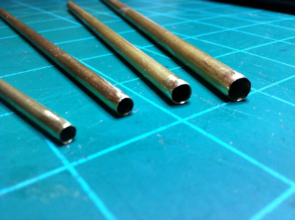
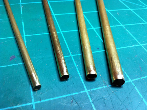
There has been many times I have needed to cut a smooth hole in a piece of foam. When I am building RC planes I normally want to cut a smooth hole to run a pushrod or wire through the foam. When I need to do this I don’t want to just shove a stick through the foam to create a hole, nor do I want to use a drill bit because that would just tear the foam up. What I do to cut nice, smooth holes in foam uses a brass tube.
All I do to cut a smooth hole in foam is simply choose a piece of brass tubing the size I want the hole, sharpen the end, and then rotate the brass tube while pushing it through the foam. This creates a very smooth hole. To sharpen the brass tube I use a fine file and with light pressure work around the edge of the tube till it’s nicely tapered. When filing, the end of the tube will sometimes start to curl in a little so I have to ream it out with a pipe reamer. The end of the tube doesn’t have to be sharp like knife-sharp, just not blunt. A nice taper works nicely.
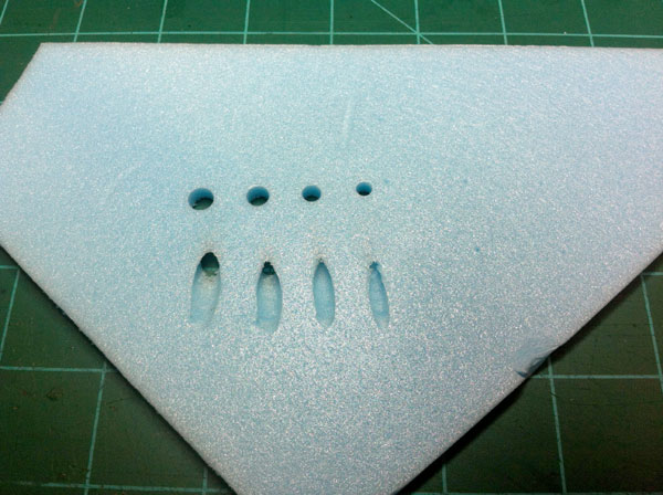
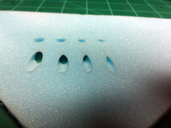
With a sharpened brass tube you can straight through holes, angled through holes, foam plugs, if you start on the edge of the foam you can cut troughs in the foam, and more. It works quite well for cutting the foam. So if you’re needing to cut a smooth hole through foam, just sharpen a piece of scrap brass tubing and try it out!
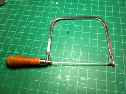
Whenever I need to cut something, the first tool I turn to is a coping saw. Whether I need to cut an intricate design out of wood, cut a shape out of brass, or cut out a rough shape of foam I use my coping saw. I normally always keep a medium toothed blade on my coping saw, but I also have rough and a fine cut blades on hand if needed.
A coping saw works great for it’s intended use: wood! I probably use a coping saw most for cutting parts out of 1/8″ plywood. It works great for cutting curvy parts out of wood. I normally just leave a coping saw on my desk for cutting wood dowels, thin pieces of wood, and plywood.
I have used a coping saw a few times now to cut 2″ thick foam. Although it leaves a fairly rough edge, it works quite well. I normally just use it to cut out the rough shape of an object and then use a box blade to finish the shaping which yields good results.
A coping saw also works good for cutting brass. Whenever I have used a coping saw on brass it has worked better than I thought it would have. It doesn’t leave a super jagged and sharp edge on the brass, but I always use file to make it smooth anyway.
One other thing about the coping saw that is one of its best features is the depth in which you can cut. My coping saw has a 6″ throat. With this feature you can cut fairly large shapes.
The coping saw can handle materials from wood, foam, brass, and more! I would highly recommend next time you see a coping saw at the hardware store or a yardsale. Go ahead and pick one up! You won’t regret it.
My brother and I recently got paintball guns and we plan to play in the woods. We haven’t played yet, but I know the secret to winning will be camouflage. If he can’t see me, he can’t shoot me. I’m starting to get my thoughts together on how exactly to camouflage my gun. The other night I thought I’d start with something easy; a camo Co2 tank cover.
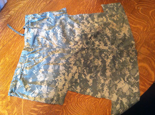
Before I get into how I made the co2 tank cover, I need to give a brief story. . . My favorite pants to wear are Army pants. They’re awesome. There are over 6 different pockets, they’re comfortable, and their camo! I normally have to wait all spring and summer till the weather is cold enough to wear them. A few weeks back I was going to go fishing and I didn’t want to have to wear my summer shorts that have only 2 pockets. I wanted some shorts that have enough pockets to fit all of my fishing gear! I went and dug out one of my many pair of army pants to turn ’em into shorts. I cut the pants at about knee length and thus had the best pair of shirts I have EVER owned!! I saved the cutoffs for use in future projects, and it was just the other day I used them to make a camo co2 tank cover.
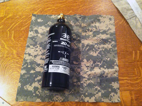
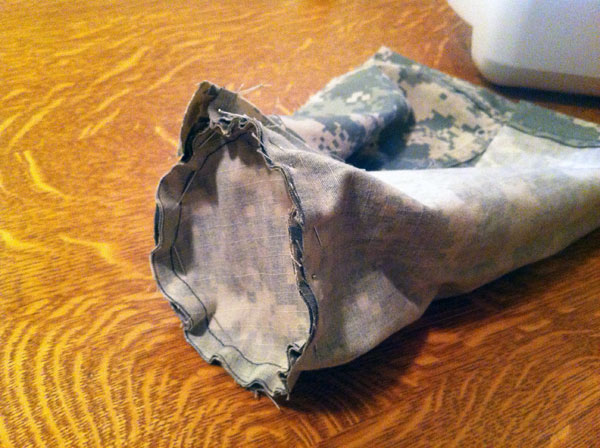
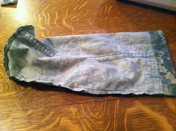
To make my co2 tank cover I took one of my army pants cutoffs and cut it down the edge to make it lay flat. I then measured the diameter of the bottom of my co2 tank. It was about 3.5″ , so I cut a 4.5″ diameter circle out of the fabric. This will be the bottom of my tank cover.
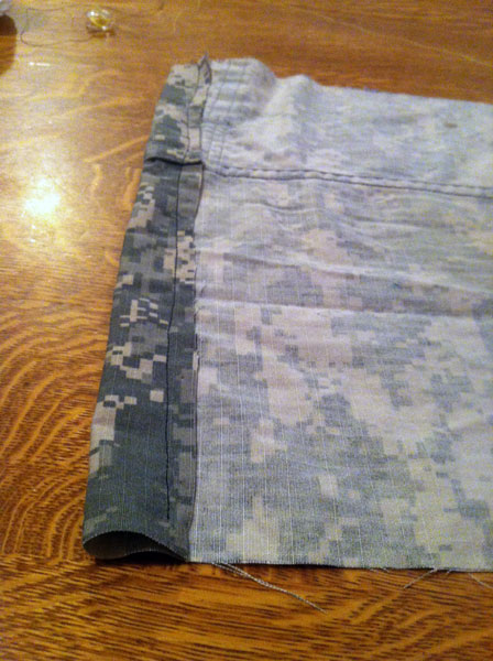
My 20oz Co2 tank is about 11″ tall but I wanted to make my tank cover longer than my Co2 tank is in case I ever want to put foam in the bottom or something. So, for the walls of my cover I cut a 13″ x 13″ square of fabric. I then cut a strip of my fabric square with the width being the circumference of my tank plus and inch or two. When I had this piece cut out, I folded over the top inch of fabric onto itself and sewed it. This fabric ‘tunnel’ will be where a draw string will go later on.
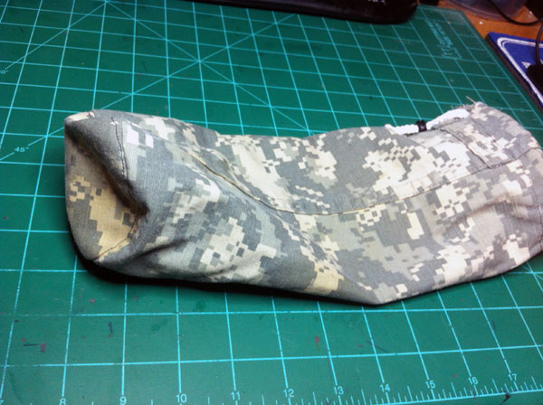
At this point I took my fabric circle and the 13″ long piece that will be the walls of my cover and pinned them up in the way that I planned to sew them. I had the wall pinned around the edge of the circle bottom piece, and I also had the wall pinned up along where the two ends met. All of this was inside out though, because after I sew it, I will flip it right side out and then no one will see my seams. After it was all pinned up, I fired up the sewing machine and sewed ‘er all up. I didn’t however, sew through my fabric tunnel because if I did it would be impossible to get a draw string through it.
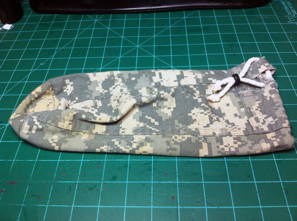
At this point I had a usable cover. I flipped it right side out after sewing and it fit my Co2 tank well, although it was slightly longer than I had hoped for it to be. The only thing I had to do at this point was to put in a draw string. I went and found me a short piece of small white rope and, with the aid of a piece of wire, I fished my drawstring through the drawstring tunnel. My drawstring worked well, but I didn’t want to tie it to keep it tight, so I found me a small rubber grommet and shoved the ends of the rope through the grommet. It was very tricky to get the two ends of the rope through the grommet because of the size of the grommet, but it worked just like I wanted it to. When I pull my drawstring tight, all I have to do is slide my tight rubber grommet down to the fabric to hold the rope from slipping and my cover getting loose.
That is it! Not hard to make at all. It took me all of about 45 minutes to do. It would probably take someone who’s more familiar with sewing much shorter, but that was my first time to sew something like that, and the first time for me to use a sewing machine. But I’m really happy with the way it turned out. I just hope it helps me stay hidden when I’m playing paintball!
I have always been fascinated with catapults. Although I have built probably over a dozen, I haven’t built one in a long while. So one night over the past week I was sitting at my desk and saw my container of airsoft BBs and thought to myself that I had never made a catapult to throw airsoft BBs. At which point I began working on building a small, desktop catapult.
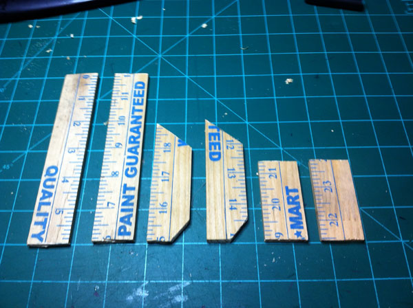
This catapult is made from a 50cent yardstick from Wal-Mart and is torsion powered. Torsion power is where energy is stored in a twisted rope and then that energy is released to move the throwing arm. Let’s begin with cutting the yardstick to make the catapult.
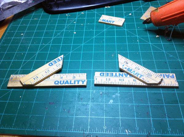
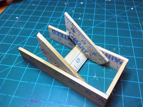
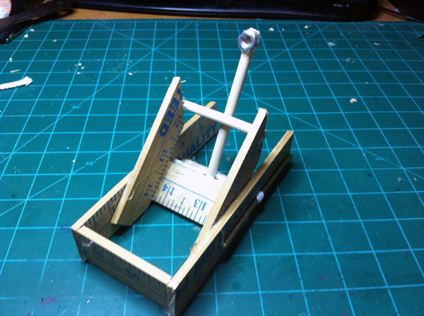
I cut two 6-inch pieces of yardsitck, two 4-inch pieces, and two 2.5-inch pieces. I began by cutting some angles in the four inch pieces and then hot gluing them onto the six inch pieces. The six inch pieces are the bottom and sides of the catapult and the four inch pieces are like a gusset that will eventually have a piece of wood glued to them that the throwing arm will hit, which will launch the projectile. After Gluing the four inch pieces to the six inch pieces, I then glued the two 2.5-inch pieces in-between the two 6-inch pieces to set the distance between the sides of the catapult. Before I started to string the rope I glued a piece of wooden dowel to the gussets of the catapult, this is the piece that the throwing arm will slam into causing the projectile to fling forward.
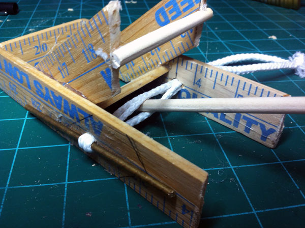
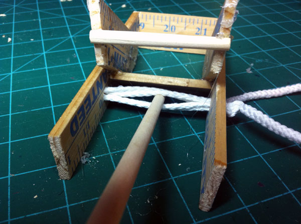
At this point I strung the rope which will give my catapult power. I did this by drilling a hole in both sides of the catapult about 1/4″ or so in diameter. I then ran one solid piece of rope through one hole (hole A), then rat it through the other hole (hole B), then looped the rope around a metal rod, then ran the rope back through hole B, then through hole A, then looped the rope around another piece of metal rod, back through hole A, through hole B, around the rod, through B, through hole A, and then tied it. Please look at the picture for this, I’m sure that is very, very confusing! At this point I had, between the sides of the catapult, four ‘pieces’ of rope. I took a piece of 1/4″ or so diameter wooden dowel and stuck it in the middle of the four pieces of rope. Then, on the outside of the catapult, I turned the metal rods that the rope is wrapped around to tighten and twist the rope. While tightening the rope I realized that I needed a strengthener in the middle of the catapult so that the tension of the rope doesn’t bust my wood, so I stuck a piece of wooden dowel in there. I continued to tighten the rope until it was tight, but did not break the catapult. Now all I needed was a ‘cup’ on the throwing arm to put the ammunition in.
For the cup that the BBs will sit in before being launched, I used a 1/4-20 nut. I hot glued the nut to the throwing arm real well because I didn’t want the hard, metal nut come flying off instead of a light, plastic BB. After this, I did all the little finishing touches: I cut the throwing arm dowel to the appropriate size, I trimmed the rope ends, and most importantly I test fired it. The catapult worked great! I was really surprised on how much power the the twisted rope delivered. The airsoft BB went flying when I let it go. I do warn you though, if you make one of these I really recommend using safety goggles when firing the catapult. I didn’t at first, but when I shot the catapult at a target about 20 feet away and the BB bounced all the way back to me, I quickly went and found me a pair of goggles.
One of my favorite hobbies is to fly remote control airplanes. I normally fly electric planes so I am always having to charge batteries. I use LiPo batteries for my planes and I have heard that they have the potential to be dangerous if not monitored well. I read that if something goes wrong in the battery they can catch fire and easily burn down a house. I try to be as safe as possible on most things and charging LiPo batteries is no exception, so I made a charging box for my batteries.
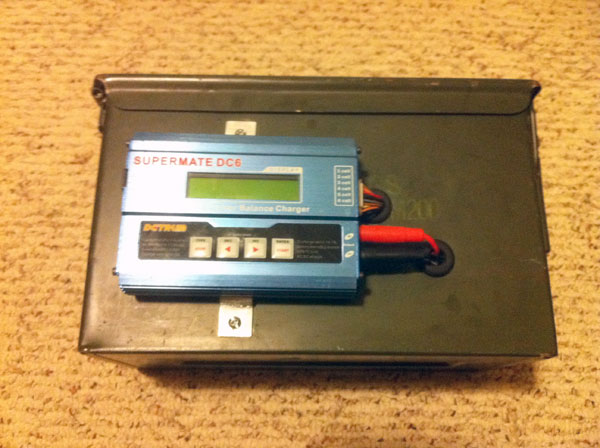
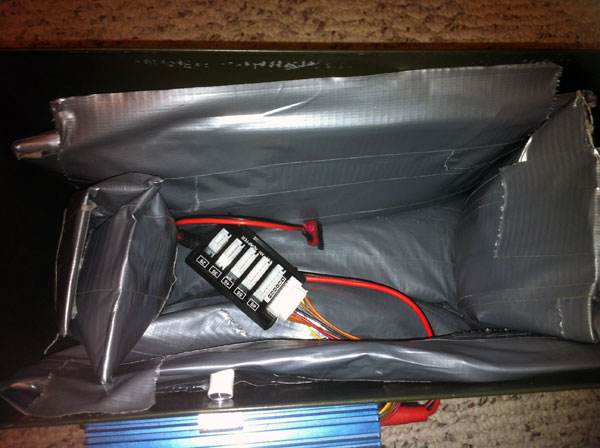
My charging box is constructed from a military ammo box I got at a yardsale. This box is great for charging my batteries in because it is made very well. It is made from metal with a heavy duty lid that can cam down really tight. If I had this box sitting on something inside my house and a battery catches fire inside the box, I’m sure that the box would get hot enough to potentially cause a fire outside of the box. To remedy this, I lined the walls of the box with sand bags.
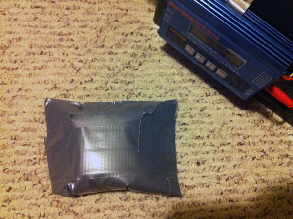
The sandbags are super simple to make. I just took some sand and poured it into some Ziplocs. I did, however, cover the ziplocs with duct tape before I put the sand in them. I did this because I didn’t want the ziplocs to tear and sand get all inside my house. The ziplocs serve two purposes, like stated before they will help absorb heat in case a battery catches fire. It also serves as a built in ‘fire extinguisher’. My hope is that if a LiPo catches fire in the box, then the fire will melt through the duct tape and ziploc and the sand will pour onto the lipo and smother it and hopefully extinguish the fire. Now I have never tested this, nor do I hope to ever find out if it works, but it is a precautionary step that I have taken.
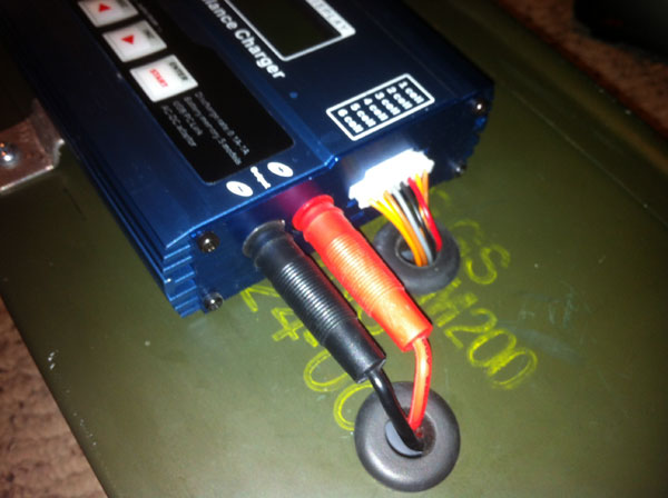
To charge the battery I need a charger in of the equation. The charger I use is a Dynam Supermate DC6. I mounted the charger to the outside of the box by bending some aluminium into little brackets that stick into the heat sink fins of the charger and also bolt to the wall of the ammo box. To get the charging wires from the charger to the battery I drill two holes in the side of the box with a step drill. I did not want the wires to be cut by the edges of the holes I drilled so I put a rubber grommet into each hole. I then stuck the wires through the holes and I was ready to charge.
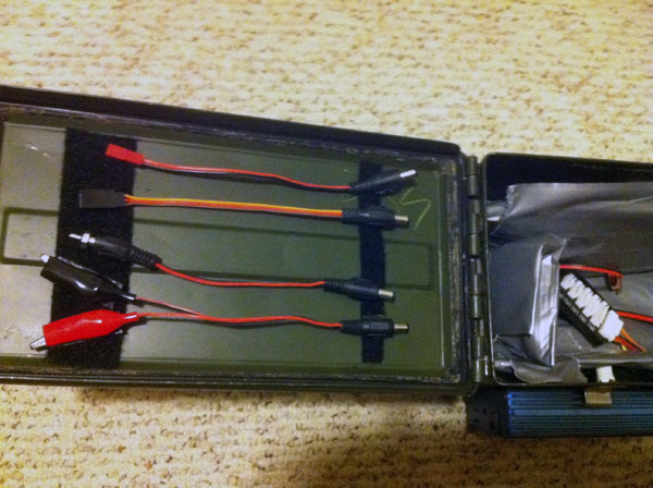
One extra thing I did to the box was I added some velcro to the inside of the lid so that I could store all of the charging leads that came with my charger more easily. Now my different leads are always right in my charging box where I need them.
Here are some pictures (sorry for the poor quality, I had to use a different camera) . . .
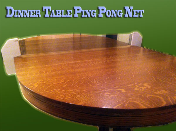
I really like to play ping pong. The only problem for me is that there is just no room in my house for a ping pong table, so I don’t get to play very often. I realized that the dinner table at my house is pretty big and would probably suffice as a ping pong table. To play ping pong on my table I would need a net, and if I had a net I would need brackets for the net. So today, I’m going to show you how I made some brackets that go on my dinner table that turn it into a ping pong table.
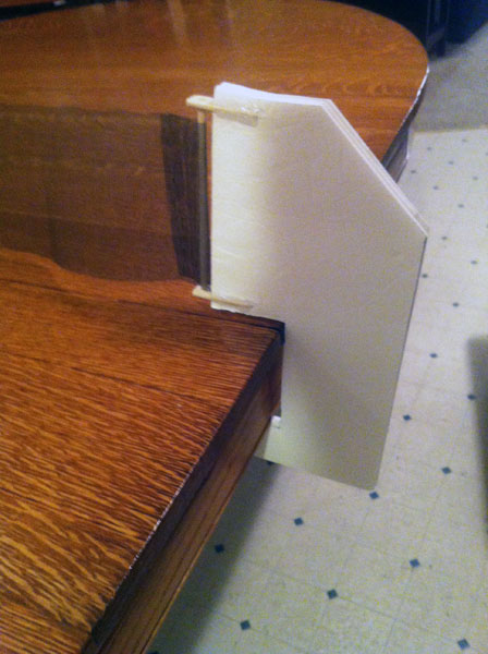
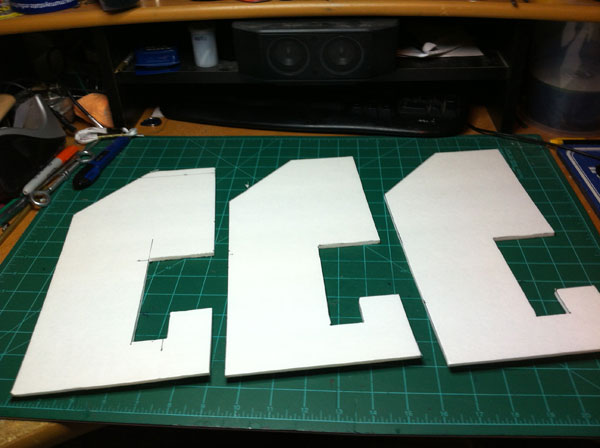
The number one criteria that my net brackets had to meet was that they could not damage the wood of the table in any way. So that means no clamping to the table, no sharp corners, no hard materials that could dent the wood. Nothing could hurt the table. With this rule in order it caused a bit of some engineering difficulty. After thinking about it for a while I came up with the idea of using the apron of the table to hold the brackets in place. The brackets hook onto the apron and then lay on the table (see pictures). I also decided to laminate three layers of dollar-tree foam and use that for the brackets. Using the foam is good because it is soft and cannot damage the table in any way and, because it is three layers of foam plus the paper, it is incredibly strong.
The net is 6 inches tall and made out of window screen. I found the easiest and best way to cut the net was to roll the window screen up and then cut the roll. This was much easier than cutting the whole length of the window screen. I then took the ends of the net and doubled them over to make a loop. I then stapled the screen to itself to secure the loop. I did this on each end of the net.
To attach the net to the bracket I mounted two ‘tabs’ made of 1/8″ plywood to the bracket and drilled a hole in each one. A wooden dowel slips into the holes in the tabs and the loop on the end of the net goes over the wooden dowel. I did this to each bracket.
I’ve played (and won 😉 ) multiple games on the table using this net and it works great! It’s very easy to put up and take down, and best of all, it doesn’t damage the table at all!
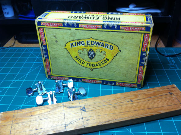
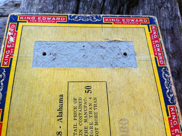
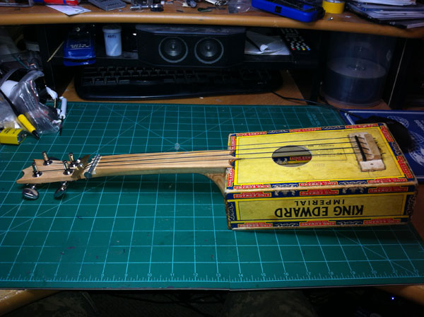
A couple of months ago I picked up a few cigar boxes at a yard sale for three bucks. I got them because they seemed great for projects and mainly to make a cigar box guitar at some point. So I guess it was about a week and a half ago I was sitting at my work desk bored trying to find something to do when I remembered my cigar boxes. I got ’em out and started making plans to build a cigar box guitar. . .
So after doing some quick researching, I realized that my boxes were too small for a normal sized cigar box guitar so I decided to make a cigar box ukulele. After I got the ukulele measurements I needed (vibrating string length, fingerboard length, fingerboard width, etc.) I started working on making the neck of the ukulele.
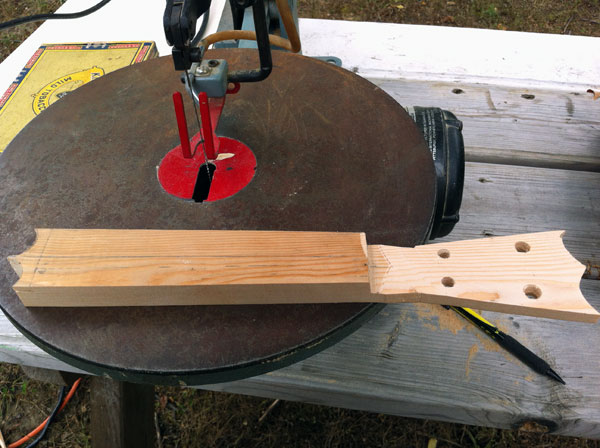
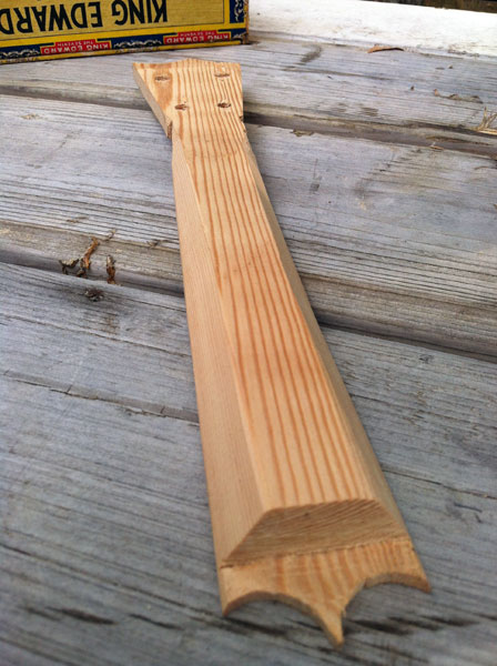
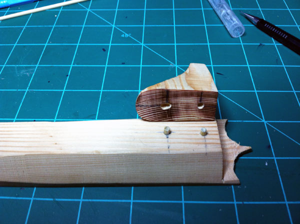
Neck of the Ukulele
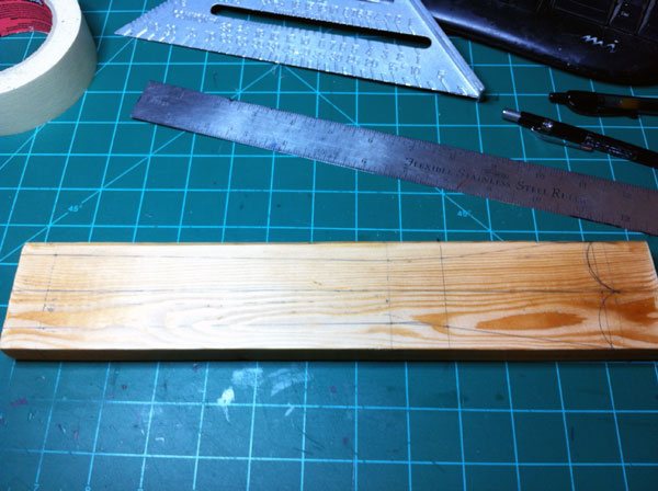
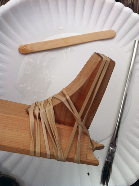
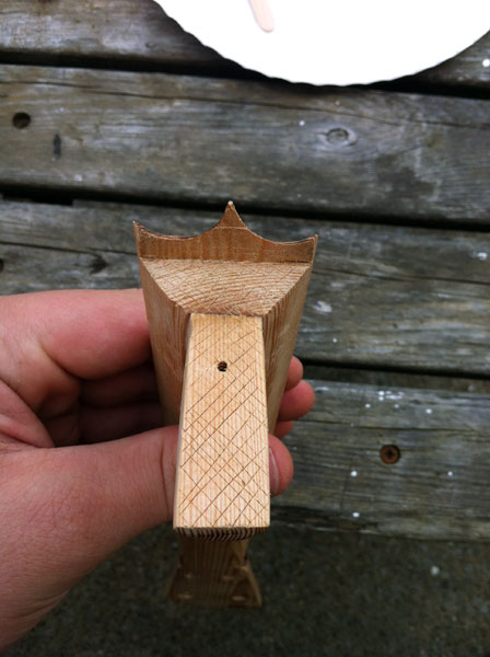
I made the neck of the ukelele from a piece of 1×3 inch pine. I find it kinda funny that I made the neck of my uke from pine and my cigar box is cardboard because it’s the exact opposite of what people say to use on the Internet. I actually read multiple places to “not use a cardboard cigar box” and to “stay away from using soft woods like pine for the neck of the instrument”. Anyway, back to the neck construction. I took my piece of pine and drew out the shape of the neck/head and cut it out with a scroll saw. I cut down the head of the instrument so it was only half of the thickness of the rest of the neck. I did this so when I install the machine tuners and strings, the tuners will be lower than the fingerboard/nut. I want them lower than the fingerboard, and more importantly the nut, so when the strings are tight they will be pulled against the nut which will in turn make the instrument sound better. Around this time I ran to the local music store and asked the luthier if he had some used machine tuners that he’d sell for cheap. I walked out with a set of used banjo tuners for $8.50. When I got home I marked where the tuners would go and drilled the holes to mount them. After drilling the tuner holes, I began sanding. I took a belt sander and sanded an angle on the back side of the neck – the angle is probably roughly 30 degress or so. I then sanded the whole neck with a 220grit piece of sandpaper. Using another piece of 1×3″ pine I cut a curved piece of wood that was around 2×1.75″ (see pictures). This piece is to glue to the bottom of the neck and ultimately to glue to the side of the cigar box for a very strong joint. To have a good bond between this piece of wood and the bottom of the neck I put in two wooden dowel pins. I glued the two pieces together with 30minute epoxy. When the glue joint between the neck and the small curvy piece was completely cured I did some last shaping of the neck assembly with my Dremel and a sanding band. At this point I was done with what I could do with the neck.
Cigar Box Preparation
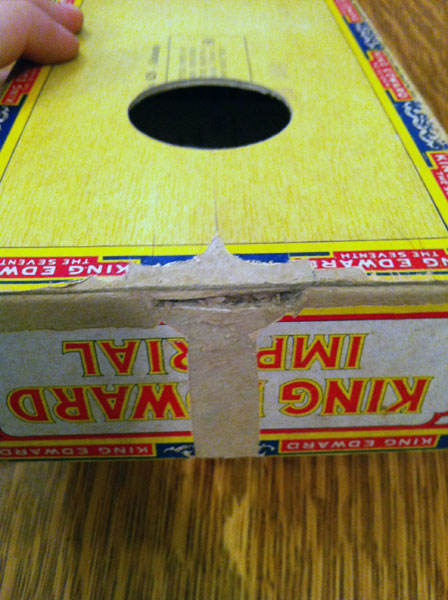
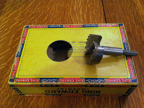
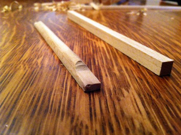
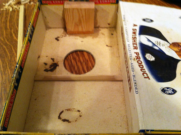
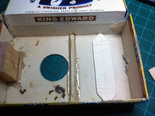
Before I could glue the neck onto the cigar box I had to do some work on it. The first thing that needed to be done was to glue a piece of wood on the inside of the box where the ukulele’s neck will be glued. This gives strength to the cardboard and a place to put a screw that will also hold the neck to the box. Another thing I did so I would have a strong joint between the neck and the box was I peeled up the outer paper on the box where the neck will attach. I did this because the cigar box is kinda old and I felt like the outer layer of paper would want to just peel off when the neck was under pressure. I then used my Xacto knife to score this area so the epoxy will have more surface area to bite to when I go to glue the neck to the box. I also scored the neck where it will mate with the box edges. The next step in the process was to cut the sound hole. I’m very glad that I had an extra cigar box because I used one of them to find the best way to cut the sound hole. I ended up using a 2 inch forstner bit to drill out the sound hole. I found the way that gave the cleanest edge was to use a drill press and to drill about half way through the cardboard from the inside of the box and then drill the rest of the hole from the outside of the box. This gave me a very nice edge and it didn’t rip or tear the carboard. For the record I moved the drill press very slow and had it spinning at 1100rpm. After cutting the sound hole, I took a piece of square dowel, cut it to the width of the cigar box, and then whittled it down a little bit. I then epoxied this into place just behind the soundhole on the inside of the box. This dowel is for strength and it should minimize flexing of the top of the box when the strings are pulling on it.
Ukulele Saddle and Bridge Assembly
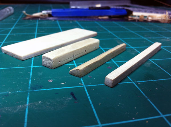
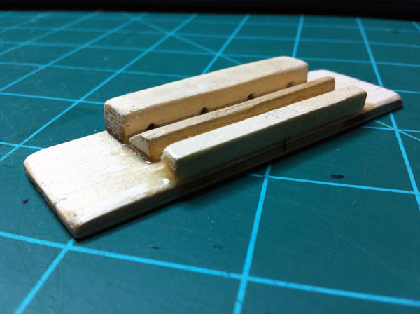
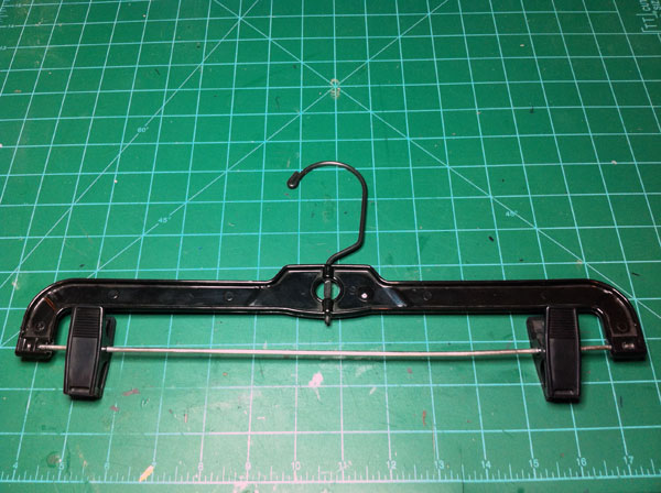
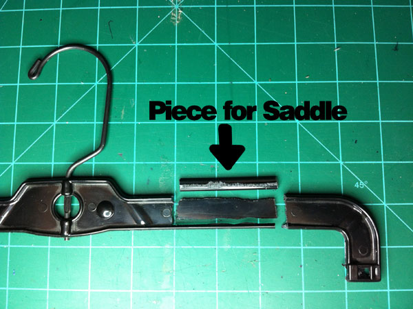
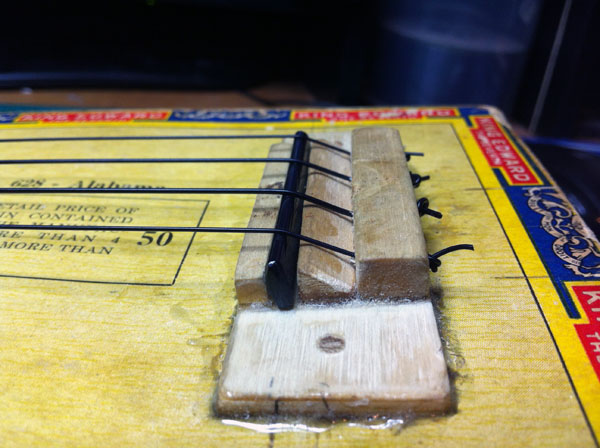
My ukulele bridge consists of a piece of 1/8″ plywood and various sizes of square wooden dowels. The base of the bridge is made of 1/8″ ply and the measurements are 1×3″. I made the tie bar of the bridge out of a piece of square dowel that I drilled 4 evenly spaced holes into. For the front of the bridge that holds the saddle in place I just used a small square dowel – I didn’t measure it but it’s probably 1/8 x 1/8″. For the other piece of wood that also holds the saddle in place I used a 3/8″ square dowel that I whittled down to 1/8″ tall and had it slope down a little. I had that piece angle because it makes it much, much easier when putting the strings on the ukulele. I then scored all of the mating surfaces and glued it all up with 30min. epoxy. While the epoxy was curing I began working on the saddle. Saddles are normally made of a hard plastic or the like. I didn’t want to spend money to have one cut at the music store so I made mine out of a coat hanger. I took the coat hanger and cut out a piece of plastic and then filed it smooth. I also filed the bottom of the saddle flat so it would have the maximum amount of contact area with the bridge because this is how the string vibrations get channeled into the instrument’s body. When the bridge assembly was all cured I began to mount it to the top of the cigar box. On the inside of the box, right under where the bridge will be attached, I mounted a piece of 1/8″ ply that spanned the width of the box. This was for extra strength because this is where all of the string’s pulling force will be exerted. I then placed some pins that went in between the 1/8″ ply plate on the inside of the box and the bridge. Then I epoxied the bridge on the top of the cigar box and inserted the saddle.
Neck and Cigar Box Glue-Up
At this point it was time to go ahead and glue the neck onto the cigar box. Like I said before, I scored both the cigar box and the neck’s mating surfaces for gluing. I then drilled into the block that is epoxied to the inside of the box and into the curvy part of the neck. I then epoxied up the box and the neck and ran a screw through the block in the box and into the the neck. I then left it to cure.
Finishing It Up
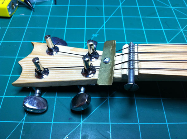
After the neck was done curing it was time to do all the little things to finish up the ukulele. Let me just say first though, up until this point I planned on installing frets on the instrument, but after realizing that I cut the neck at an angle, I figured it would be near impossible to get the fret wire installed perpendicular to the strings. If I had the frets just slightly off it would mess up the intonation of the instrument and I wouldn’t be able to fix it. So I just kept it fretless. So to finish up the uke I installed the machine tuners and installed the nut. For the nut of the ukulele I used a screw that was just lying on my desk. I got the idea from this awesome book I got at the library called “Handmade Music Factory”. The book has step by step plans for making homemade instruments. Some of which I may be building in the next few months. When I was messing around with my ukulele I noticed that the lid kept wanting to open so I put a screw through the lid and into the block that the neck is mounted to. Then I strung all the strings and tuned it. The tuning of a soprano ukulele, from the string closest to the floor to the string closest to your face when playing it, is A-E-C-G. After tuning ‘er up, I started plucking around on it. It actually sounds better than I expected! That doesn’t mean it sounds great at all, I mean it just sounds good for a cardboard box – haha. Below is a video I made with me playing the ukulele (and the guitar as accompaniment ) so you can hear what it sounds like!
What I would do different
If I built this ukulele again, knowing what I know now, there would be a few things I would do different. The first being the frets. I would’ve cut the fret grooves before even cutting out the shape of the neck. I also would’ve taken more care when gluing the neck to the box. I took my time to make sure that the neck was glued right in the center of the box and 90degrees with the box when looking from the top of the instrument, but I didn’t look from the edge of the box. I ended up gluing the neck at an angle when looking at the edge of the box so now when the strings are strung the distance from the fingerboard and the strings gets larger and larger as I go up the fingerboard. If I had to do it again, I would also and the head of the instrument downward so the machine tuners are even lower in comparison to the nut of the instrument. They way they are now is not low enough so when I played the ukulele the strings would buzz on the nut. To fix this I had to put a bolt threw the head with a piece of brass on it to pull the strings down upon the nut. This fixed the problem, but it doesn’t look great.
I had a few projects that I could have wrote about for today, but I thought I’d give an update on some past projects and a few new things that have to do with the website.
;
Website I don’t know if any of ya’ll have noticed, but over on the right of the webpage are three new buttons that link to my Facebook page, YouTube channel, and a link where you can sign up to get my RSS feed. So if any of ya’ll want to get my status updates you can like my Facebook Page or if you want to see when I upload a new video to YouTube you can do so by subscribing to my YouTube channel! For those who follow RSS feeds on your smartphones, you can sign up for my RSS feed so you can see whenever I post a new blog entry. If you want, you can do all three! 😉
I’ve also designed a logo, updated the banner at the top of the page, added collapsible categories, and I’ve been trying to do better graphics for each blog post. I’m going to continue adding more small stuff like this to help improve the functionality, usability, and appearance of the website. If you have any advice/tips you can email me them ( backroomworkdesk@gmail.com )
I bought a gallon of gas at a hobby shop a few weeks back for a .40 size engine I have on an RC plane. I haven’t looked into it enough to find out if it will work for my .049 engine, but if it does I may be trying to start it soon. I just wanted to let ya’ll know that starting the engine is still on my list of things to do. With school starting back it may be a while till I find the time to do it, but like I said it’s still on my list.
I have had a few new ideas on how to build a firecracker dispenser that hopefully won’t jam. I’m still in the middle of working the kinks out in my mind and then I will built a prototype or two. A guy named “Haunce” left me a comment on one of my firecracker dispenser blog posts with an idea about just using an electrical system to ignite and drop the firecrackers. It sounds like a very good idea and I’ll be toying around with something like that soon too.
In my last blog post about this boat I said I just needed a battery to run it. I ended up finding a battery at a yardsale for cheap. It was a 7.2v 1800mah NiCad battery that worked very nice. So after doing multiple tests just in the air with the boat, I charged up the battery again and headed out to the pool. I sat the boat in the water and gave it just a little throttle and it started to go. I gave it just a little more and then the boat jumped to full throttle for like 1/4 of a second and then completely stopped. As the boat jumped shut off I got a very bad smell as the magic blue smoke that is inside all electronics escaped from the ESC/BEC. I guess with the resistance of the water, the motor was pulling too many amps for the ESC/BEC and it fried. So now I’m in the market for a new brushed ESC with a high amp capacity. Whenever I get a brushed ESC I will try ‘er again and see what happens.
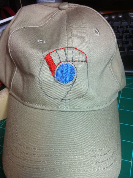
This is kinda different than most of the projects I’ve posted on here before. Normally my projects have something to do with actually building or designing something, but this week it’s about sewing. To be more specific, this post is something I embroidered.
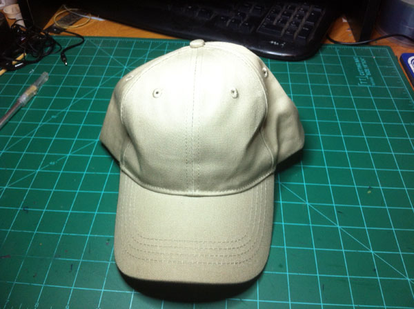
Google is my favorite company ever. They make great products and treat their ‘customers’ awesome. Along with that, Google Chrome is my favorite internet browser! It’s the fastest and most reliable internet browser I have ever used! I went searching the other day for a Google Chrome ball cap and I found one on Google’s online store for about $9. I thought this was a great price, but I felt like I could make my own. Now I have never embroidered or really done any sewing before in my life so I knew I would have to learn something new. . .
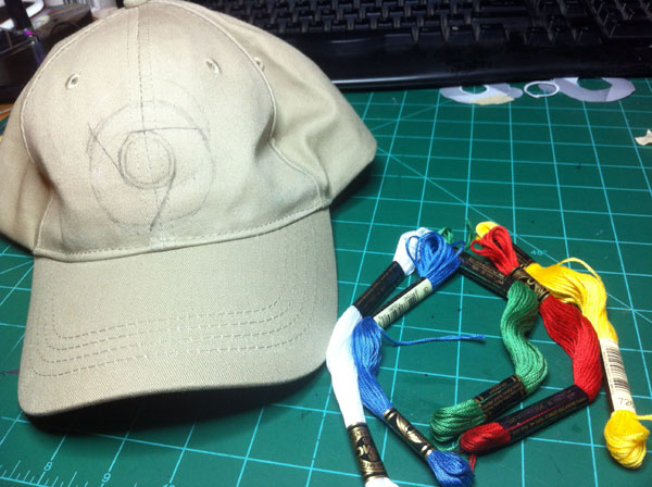
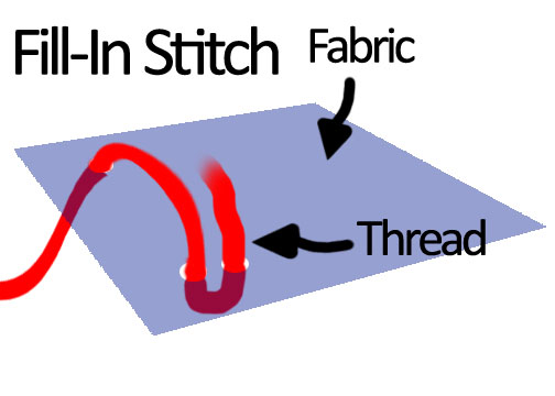
So I went to Hobby Lobby, bought the assorted colors of thread (I later learned that this was technically called “floss”) and some embroidery needles, and then came back home to figure out how to embroider. After doing some Google-ing on simple embroidery stitches and sewing stitches I got kinda confused. There were sooo many different stitches that I had no clue which one to do! I knew I wanted a stitch that would go around the outline of each color, and another stitch to fill in the outline with. I decided on a simple backstitch for the outline of each color and to fill in each color, I kinda came up with my own stitch. For the ‘fill-in’ stitch all I did was come up with the needle from the back of the fabric, pulled the floss though, and then went through the fabric again about 1/4″ away from where my needle originally came up through the fabric. (See drawing below) I used this stitch to fill in all of the colors.
Another thing I want to talk about is using a hoop. When I was researching embroidery I read on almost every page that I needed an embroidery hoop. Not true. I did not use a hoop at all when I made this hat. Now if I was embroidering, let’s say, a T-shirt then yeha, I’d probably need a hoop to keep the fabric taut. The fabric that the hat is made out of is stiff enough to not use a hoop with (or at least I had no problems with not using a hoop). Now there are some wrinkles around the logo that probably wouldn’t be there if I had some type of hoop that I could put a hat into, but I’m fine with that. I’m pretty sure they will work themselves out eventually. If not, I can just iron it.
One last thing I want to mention before I end this post is about backer material. As I was surfin’ the web on how to do embroidery I read little bits here and there on using backing material when embroidering. I did not really understand what this backing material gained me and I didn’t find a clear cut answer, so I just didn’t use it!
With all that being said, I know this isn’t the best embroidery job ever done and some of you out there who embroider often may laugh at it, but that’s okay. It was my first time to embroider and I’m happy with it. I’m just glad I now have a Google Chrome hat! 😀
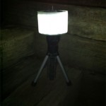
Over the weekend I went night fishing with my family. When you go night fishing you want to set up lanterns to attract bugs. The bugs attract small fish, the small fish attract bigger fish, and those fish attract even bigger fish (the ones you want to catch). So having a lantern is pretty important. My only problem is we only had one lantern, and when you’re fishing with four guys spread across a 16ft boat one lantern just doesn’t cut it! So I went and grabbed my favorite flashlight (a Stanley LED flashlight that has a tripod base) and made an attachment that turned it into a lantern.
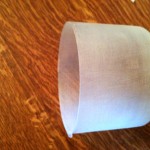
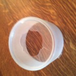
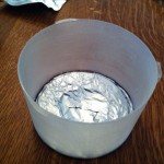
Now I’ll say right up front that this lantern attachment was done in a hurry so it might not look the prettiest (you know, cause all of my other projects look really nice 😛 ). So to make the plastic housing that creates the lantern glow I used a small CD spool cover. Since the CD spool cover is clear it won’t make a good lantern housing so we need to modify it. What we want is a piece of plastic that you can’t see directly through, but the light will shine through (we want it translucent, not transparent). To make this clear plastic more opaque I took some sandpaper and really roughed up the outside and inside of the CD spool lid. Now when the light shines the whole plastic lid will ‘glow’ and not just let the light shine right out. After I ‘opaque-ified’ the plastic I cut a hole in the bottom for my flashlight to stick through. I made this hole just the right size so it hold itself on the flashlight by friction.
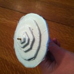
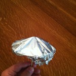
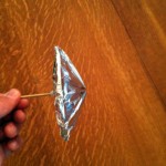
At this point I basically have a flashlight with an opaque plastic ring that slips on the top, but I don’t have a usable lantern yet because when I turn on the flashlight it just shines out the open top and gains me nothing. What I need now is a mirror on top that will reflect the light back down and out the sides. I could just put a flat mirror on top and it would work okay, but what would work best is if I had a 45 degree-ish mirror cone on top that directs the light out the sides. To make the mirror cone I cut out five circles of foam with each circle getting smaller and smaller. I stacked these foam circles on each other to make a rough shaped cone and the shoved a bamboo skewer through the center of the foam cone. I hot glued the bamboo skewer into place which also held the foam cone together. I then covered the cone with aluminium foil to act as the mirror. After trimming the aluminium foil and cutting the bamboo skewer to the right size, I stuck it into the CD spool lid so that the light from the flashlight will hit the cone right on the point and reflect onto the sides. I now have almost all of the light from the flashlight shining out the sides of the CD spool lid, but not all of it – some of the light is reflecting down and shining through the bottom. To fix this I traced the spool lid onto some more aluminium foil and cut it out. I then hot glued the aluminium foil circle on the bottom inside of the CD spool lid. This will reflect the light back to the reflective cone and that should reflect the light outwards.
When I finished it up I went into a dark room and tested it out. I was very impressed on how well it worked especially since it only took like a half hour to make. We brought it fishing and worked quite nicely for attracting bugs. This should work with any flashlight, but if you decide to make one you may need to make some type of stand if your flashlight doesn’t have a built-in tripod.