Tuna Can Oil Lamp


I was cleaning out one of my ‘junk drawers’ yesterday and I stumbled across one of my past projects, a tuna can oil lamp. I made this about, I’d say, two years ago because I wanted a flame for melting wax and just burning stuff. I really wanted a bunsen burner but, like a lot of things, I didn’t really want to spend my money on it.

Since I built this a few years ago, I will just tell how it’s constructed and not too, too much about the step-by-step process of how I built it.

So the main construction of this lamp is made from a tuna can and a Ball mason jar lid. I took the mason jar lid and band and stuck them on top of the tuna can and used a generous amount of JB Weld to adhere the lid assembly to the tuna can. I had to fill in the little bit of a gap that was between the tuna can outside wall and the lid band inside wall because I didn’t want any of the oil leaking when I used the lamp.

For the wick adjustment assembly I took a piece of sheet metal and made the housing for the spindle that raises and lowers the wick. After cutting a hole in the lid of the lamp I riveted the adjustment spindle housing to the lamp’s lid. I also used some JB Weld here too because I didn’t want the adjustment housing to come off, and it also covered some of the sharp corners of the sheet metal.

I used an 1/8″ steel rod for the actual spindle of the wick adjustment assembly. To make the ‘star’ shaped piece that grabs the wick and actually raises it up and down I used a dime. I took the dime and drilled a 1/8″ hole in the center with a drill press and then took my Dremel and cut out some of the metal to make a four point ‘star’ shape. I used JB Weld to adhere the star to the spindle. For the turn-knob I used a penny! (Yes, I used JB Weld to glue the penny to the spindle).

After all the JB Weld was dry, I poured in some lamp oil, stuck in a wick, and lit it. It worked great! I could adjust the flame size with my spindle and the oil lasted for a very long time! A few things I would change . . . . If I built this again, I would totally make the adjustment spindle stick out farther so when I adjust the flame I don’t burn my self (Ha!) and I would not have spray painted it silver. After finishing it up, I though “hmm, this would look pretty cool if I painted it silver” – it didn’t. So that’s why it looks pretty bad. . . . Never the less, I leave you with pictures. . . . . . .


Posted in Fire/Pyrotechnics, Miscellaneous Tagged ., adjustment, B, back, backpack, backpacking, backroom, buid, build, burn, camp, camping, can, com, d, deks, desk, di, dime, diy, fire, flame, home, homemade, hot, i, J, JB, lamp, made, oil, pack, penny, room, spindle, stove, tuna, Weld, work, workdesk, y

Quick and Dirty DIY Servo Y-Connector

I have been building an RC plane recently (I will post it when it’s complete) and when I went to hook up the ailerons I realized I didn’t have Y-connector to plug the servos into one channel. It was too late in the day to go to a hobby shop and I didn’t want to wait, so I made my own.

After rummaging through my RC junk box, I found a destroyed HXT900 servo. What’s good about HXT900’s is that they come with really long servo leads. I decided to use this very long lead to make my Y-Connector. After cutting the lead off of the servo I cut the lead into three equal sections. Now a Y-connector needs one female plug and two male plugs on it and since we already have the female end from the servo we will start to work on the male plugs. For the male plugs I took some straight male header pins and cut two pieces that have three pins in it. I then stripped the ends of one of my pieces of servo lead and soldered on the male header. I then repeated this for the other male header. Oh, and I used heatshrink wherever applicable.

Next I stripped the ends of the leads that had male header on it and soldered the two male header leads to each other. I was careful to solder yellow to yellow, red to red, and brown to brown. Again, I applied heatshrink anywhere I could. At this point I stripped the end of the lead that had the female servo plug on it and soldered it to the male harness. This is kinda tricky to explain so be sure to look at the pictures. Once again, I soldered yellow to yellow, red to red, and brown to brown. After putting heatshrink on almost everything, this Y-connector was completed. I tested it out and it works just fine. That’s how I turned a destroyed servo into a functioning Y-connector!


Posted in Tools Tagged -, airplane, back, backroom, build, c, connector, control, d, diy, harness, home, homemade, i, made, r, RC, remote, work, workdesk, y, Y-connector

Cool Tools: Hand Crank Drill Press

20120602-105935.jpg

Score! I got this really awesome tool at a yardsale the other day. It’s nothing I’ve ever seen before. It’s a hand crank drill press. It’s a hand crank drill with a lever to lower the drill. This drill press has stamped into it “Made In Germany”. The guy I bought it from said he thinks it was made sometime before WWII (I don’t know if I quite believe that).

I got this tool because I find it very interesting and also because I really like old hand crank tools (especially if they’re small). I don’t know how practical this tool is though, as both of your hands are tied up when using it. One hand is cranking and one is lowering the drill, therefore you can’t hold the workpiece. I don’t have a super mini drill press vice so it may be a little tricky to use this.

I still find this tool very cool, even if it isn’t the most practical. I got it for $10 which I think is a good price considering that the guy had a price tag of $100 on it! Wayyyyy too much to spend on something like that.

I don’t know too much about this tool in terms of history, so if anyone has ever seen one before or knows any history on it please share it with me.

Here’s some pictures. . .


Posted in Cool Tools Tagged :, 1, 2, antique, backroom, bit, built, cool, crank, created, desk, drill, drillbit, flea, german, germany, green, hand, i, in, made, market, metal, nostalgic, old, one, press, tool, tools, two, vintage, war, workdesk, world, WWI, WWII 2 Comments

Simple 9v Battery Clip

20120522-233725.jpg
There have been multiple times where I have needed a 9v battery lead/clip but did not have one. Just the other day I was working on a project that I wanted to hook a 9v up to and like before I did not have any 9v battery clips, so I made my own.

I made my battery clip out of a dead 9v battery. The first thing I did was take some pliers, and after finding where the battery casing ends meet, start to pry at the casing at the top of the battery. I continued to work at opening up the 9v casing to the point in which I could slide out the piece of plastic that has the 9v battery terminals on it. When I got this out I threw away the mangled up casing along with the dead cells that were in the casing.
Now it’s time to solder. I got two pieces of stranded wire to solder onto the 9v battery terminals we just saved from the dead battery. I soldered each wire to the back side of one of the terminals. When soldering the wire I realized that what used to be the battery’s positive terminal would snap onto a 9v battery’s negative terminal, and vice versa. So I planned my wire colors accordingly.
At this point the battery clip is done, but to make mine look cleaner I took some 1/2″ diameter heat shrink and stuck it over the clip. After shrinking it with a heat gun, I used an Exact knife to cut around each terminal. I think this made it look a little more professional.


Posted in Miscellaneous Tagged 9, 9v, backroom, battery, build, buy, clip, d, design, diy, easy, heat, heatshrink, home, homeade, homemade, i, lead, made, make, nine, quick, shrink, simple, solder, v, volt, wire, workdesk, y

Homemade RC Boat: Part.3

My RC boat is almost finished! I got the rudder installed and I just finished installing the stuffing tube, shaft, and motor. I now just have to get a battery to use and then I’ll try ‘er out!

To mount the stuffing tube to the boat I drilled two holes in the center of the boat about 1-1/2″ apart. I then connected cut out the piece of plastic that was in between the two holes. The stuffing tube was then just slid through this slot in the hull with the oil port facing upward. I then used a large amount of hot glue to hold the stuffing tube in place and make the hull watertight. I then removed the rudder to slide the shaft into the stuffing tube. When I got the shaft into the stuffing tube I marked where the end of the shaft comes to on the inside of the boat. I did this so I would know where the motor needed to be mounted.

To build the motor mount I took a piece of steel stock that was about 1/32″ thick and cut a rectangle out of it about 1-1/4″ x 2″. I mounted my motor to this steel rectangle and then to the boat. The first thing I did to the rectangle was cut a slot from one end about 1/5″ – 3/4″ long for the shaft to slide down into. Then I marked the holes where the bolts will go that will hold the motor to the steel rectangle and drilled them out. After bending a less-than-90° angle in the metal, I mounted the motor to the steel bracket and the hotglued it in place on the boats hull. At this point I stuck the rubber gas line onto the boat’s shaft and then shoved it onto the motor’s pinion gear.

The boat is pretty much finished. I hooked up the electronics (I ran a servo extension to the servo and plugged the motor into the ESC) and it is now ready for testing! . . . I just need a battery. When I get a battery I’ll post how the testing went, and hopefully get some video of it in my pool or in a pond or at the lake. Stay tuned!


Again, I guess I got too busy working on the boat that I forgot to take pictures. So here are the ones I do have. . . .


Posted in Boats Tagged aqua, back, backroom, Boat, brass, build, c, complete, control, d, dc, degree, diy, do, done, drive, ESC, finish, finished, grease, home, homemade, hydro, i, it, made, miniature, motor, oil, pack, packing, pitch, power, prop, propel, propeller, r, RC, remote, room, rudder, self, servo, shaft, steer, steering, stuff, stuffing, test, testing, train, tube, turn, water, work, workdesk, y, your, yourself 3 Comments

Homemade RC Boat: Part.2

Time to build a rudder for the boat. I made the rudder out of some brass sheet I got at the hardware store. To start I took my brass sheet and I drew on it the dimensions of the rudder. I made the rudder 1-1/4″ wide at the top and 1″ at the bottom. The rudder was 3″ in length. I cut out the rudder with some tin snips and then sanded it smooth. I then took a piece of the 3/16″ brass tubing I had and cut a slit in the end. The rudder was then slid into this slit and soldered. I filed the solder smooth so it wouldn’t cause too much turbulence in the water. (It probably wouldn’t cause much of a problem if I didn’t file the solder smooth because it’s just a small toy boat that won’t go too fast, but I thought I’d do it anyway) At this point the rudder itself is done, but now it’s time to mount it to the boat.


Before I made any marks on the boat’s hull, I put some painters tape on the boat. This way I could mark all I wanted and when I was done with the project I could peel up the tape and no one will see my marks. I think it looks a lot nicer in the end when I do this. So, after putting some tape on the boat, I marked where I wanted the rudder to go. I put the rudder about an inch away from the rear of the boat because I plan on having the prop somewhere around 1-1/5″ from the back of the boat. To mount the rudder I drilled a hole in the boat the same diameter of the shaft that is attached to the rudder. I then took a piece of brass tubing, and using a generous amount of hotglue, I glued it right over the hole I just drilled. (The size of tubing I glued to the boat was the next size up from 3/16″ – It was the size that the 3″/16″ tube slid into perfectly). I then glued a small piece of wire to the tube that is mounted to the boat as a brace.


When I stuck the rudder shaft through the tube mounted to the boat, it was kinda rough to turn when the rudder was pulled against the boats hull. I didn’t like this and I didn’t want to put any strain on the servo that will run the rudder so I cut a little bushing. I cut the bushing from a larger sized brass tube using my mini pipe cutter. The bushing is only like 1/8″ long but it keeps the rudder off of the boat’s hull just enough for it to move smoothly.


For the control part of the rudder I made a control horn out of a piece of the same brass stock that I made the rudder out of. It is very simple – just a ‘triangle’ piece of brass with a few holes drilled in it and then sanded smooth. I drill a large hole in the end of this control horn, stuck a piece of tubing in it, and soldered it. This tubing that is soldered to the control horn will slip over the rudder shaft. To keep the control horn connected to the rudder shaft I used a pin. To do this I slid the control horn onto the shaft and drilled a small hole through the control horn tube and through the rudder shaft at the same time. I then stuck the rudder through the tube that is glued to the hull, slid on the control horn, then stuck a pin through the small hole I just drilled.


I hot glued to the boat a large Futaba servo near the rudder. I then hooked a control rod from the servo horn to the control horn on the rudder. After hooking up the servo to the receiver, I got the rudder trimmed out straight. I now have a steering control made for my soon-to-be boat.


Sorry, but I guess I forgot to take more pictures during the rudder build. Here are the pics I did take though . . .


Posted in Boats Tagged aqua, back, backroom, Boat, brass, build, c, control, d, dc, degree, diy, do, drive, grease, home, homemade, hydro, i, it, made, miniature, motor, oil, pack, packing, pitch, power, prop, propel, propeller, r, RC, remote, room, rudder, self, servo, shaft, steer, steering, stuff, stuffing, train, tube, turn, water, work, workdesk, y, your, yourself

Homemade RC Boat: Part.1

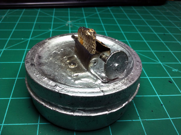
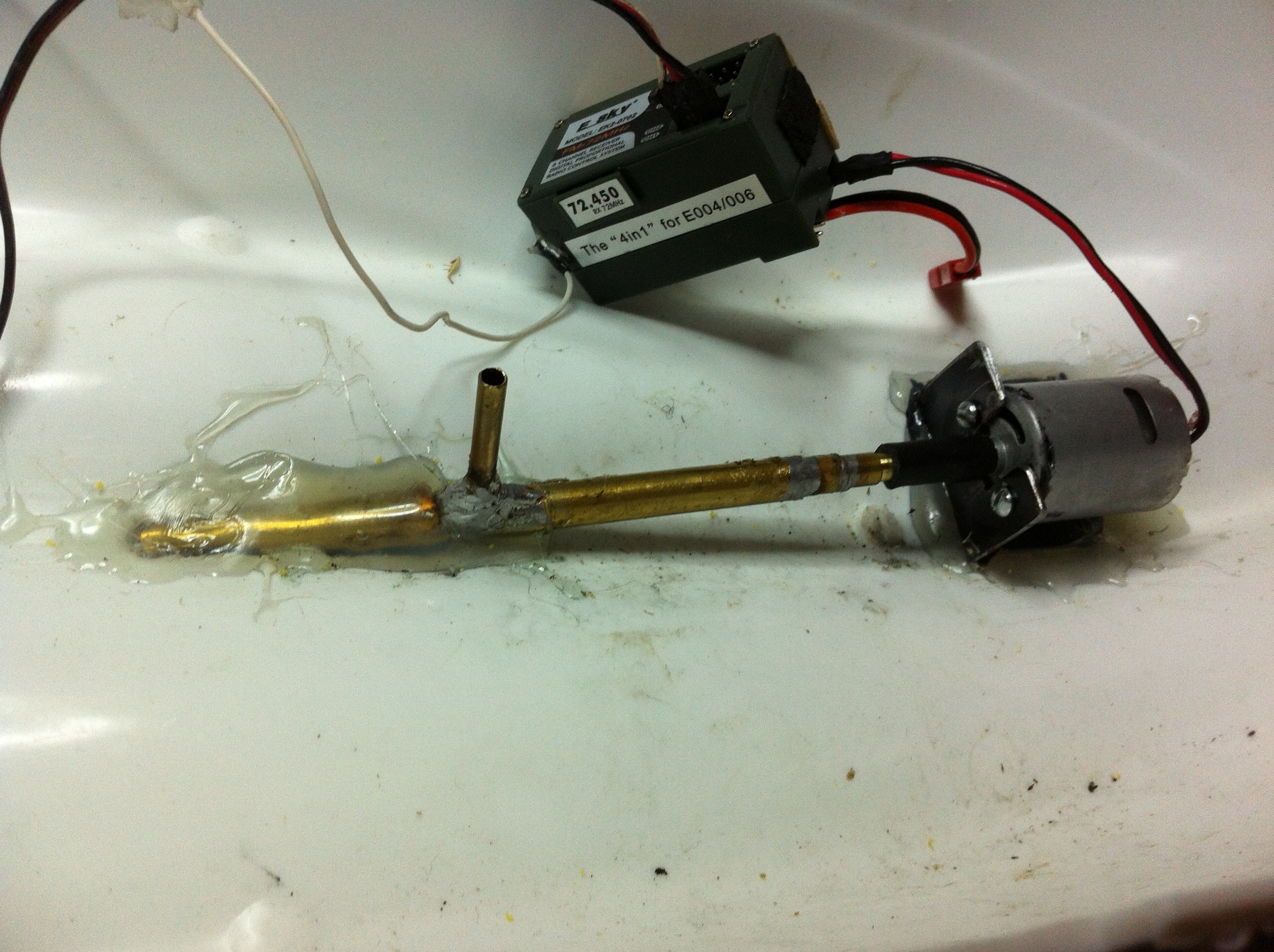
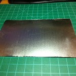
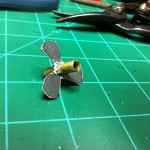
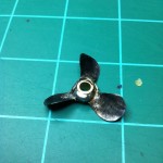
So I already have a boat prop, but now it’s time to build a boat for it. My plan is to build a very basic boat I can use in my pool. I will use a cheap toy boat from Wal-Mart as the hull, a DC motor that I saved from my destroyed RC helicopter, a 4-in-1 receiver box from the same helicopter, an old futaba servo, and I will use the transmitter that came with the helicopter.

After doing some research on RC boats I found that there are two common ways of connecting the motor to the prop. The first is direct drive – this is where there is a universal joint at the motor that is connected to a solid shaft that goes through a stuffing tube. After coming out of the stuffing tube there is another universal joint which is followed by a threaded rod that has the prop on it. The universal joints are so the motor and prop can be parallel to the hull but the shaft can be angled. The other method uses a flex shaft so the stuffing tube can be curved. The motor and prop are still parallel with the hull, there are just no universals. I will be doing my own version of the solid shaft method. There will be no universals joints, per se. On the prop end there will be no universal at all. It will just be the shaft with the prop on it. This means the prop will not be parallel to the boat. I thought long and hard on how to connect the shaft to the motor – I was worried that if I had no universal and just mounted the shaft directly to the motor that I would have to mount the motor in the exact angle of the shaft or there might be problems. I really didn’t want to do this because I didn’t want to have to worry about mounting it perfect. I knew I needed some type of universal, but just didn’t know what I’d use. I toyed around in my mind with the idea of using a universal joint that you would use with a 1/4″ ratchet/socket, but I didn’t like it too much. If I couldn’t think of anything else I would’ve done that. As I was thinking about how to connect the two, some gas line that was laying on my desk caught my eye. Yes! I could just slip the 1/8″ rubber tubing over the pinion gear on my motor and then onto my shaft. The rubber will act as a good enough universal so that I could mount my motor a degree or two out of line of my shaft and still be okay. I knew this would work well for me, so I went with it.

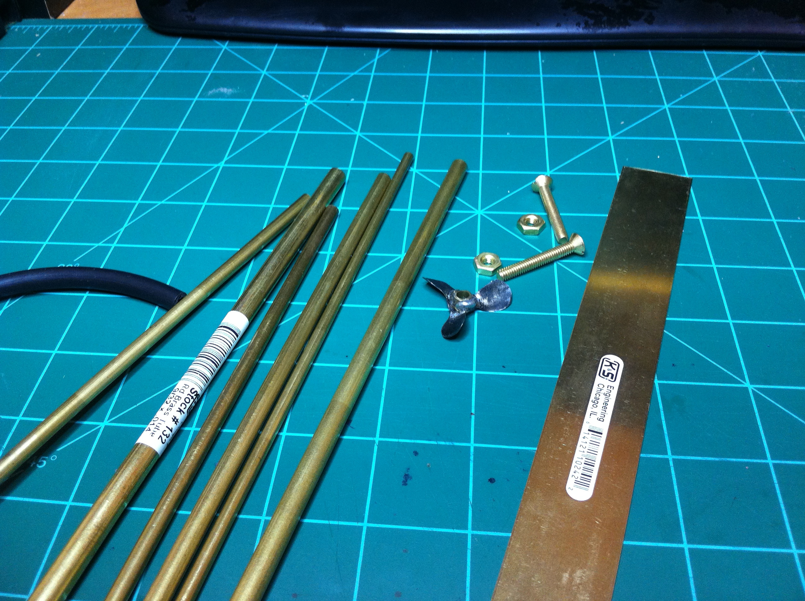
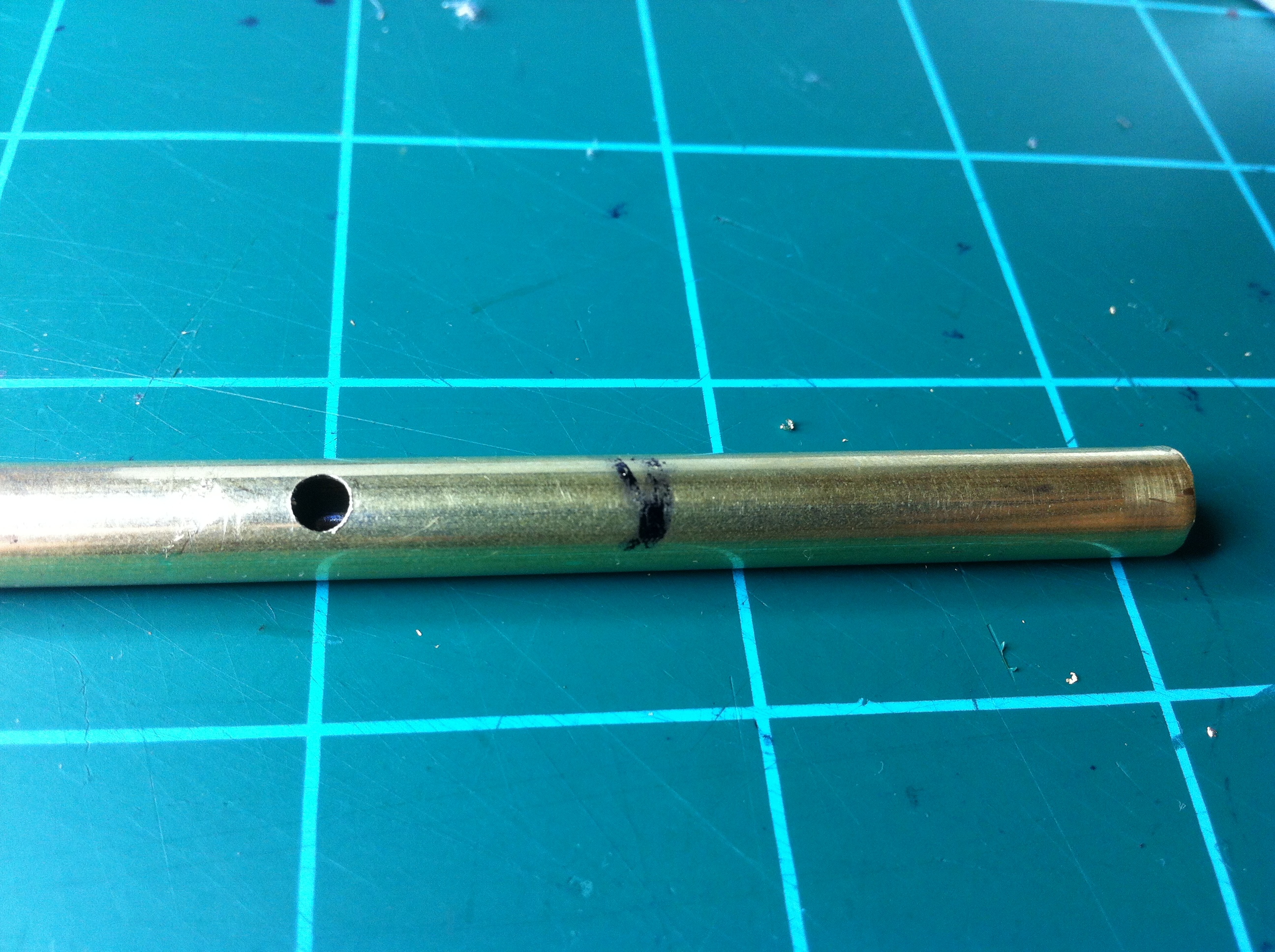
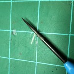
Next time I got to the hardware store I went to their awesome K&S engineering stand for brass tubing. I decided to use 3/16″ brass tubing for the shaft because it would give me a snug fit when I pressed it into the 1/8″ rubber tubing. I bought a 3/16″ tube (the shaft) and the next three larger sizes of tube that telescoped well. I didn’t really pay attention to the dimensions as they were unimportant to me, I just needed them to fit inside of each other snugly. These three pieces of tubing will make up the stuffing tube.

Shaft
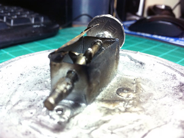
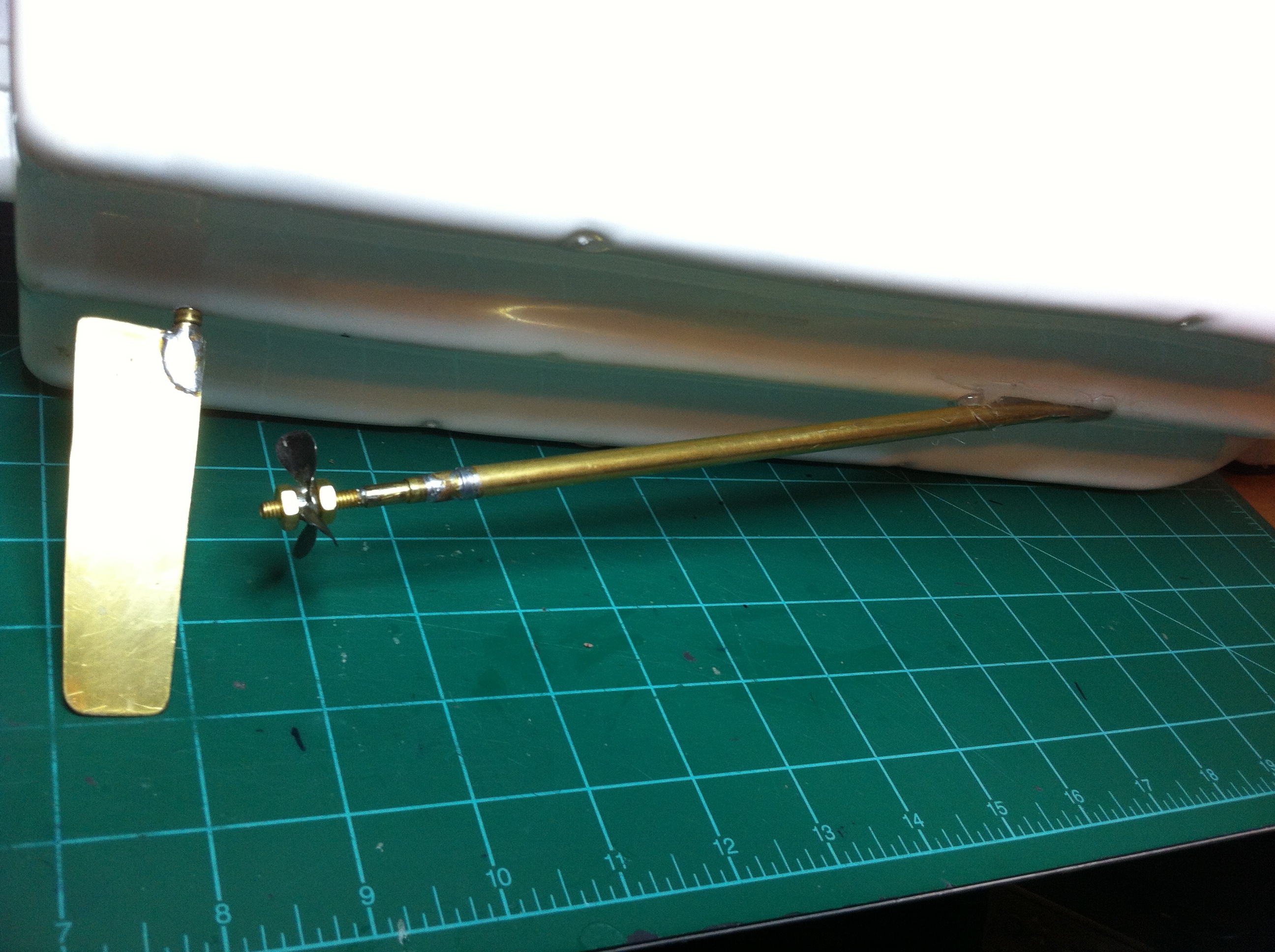
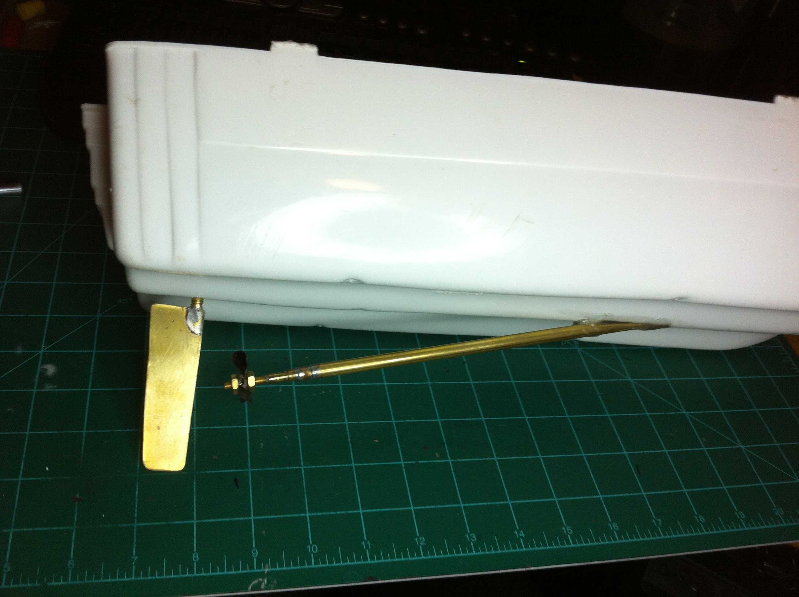
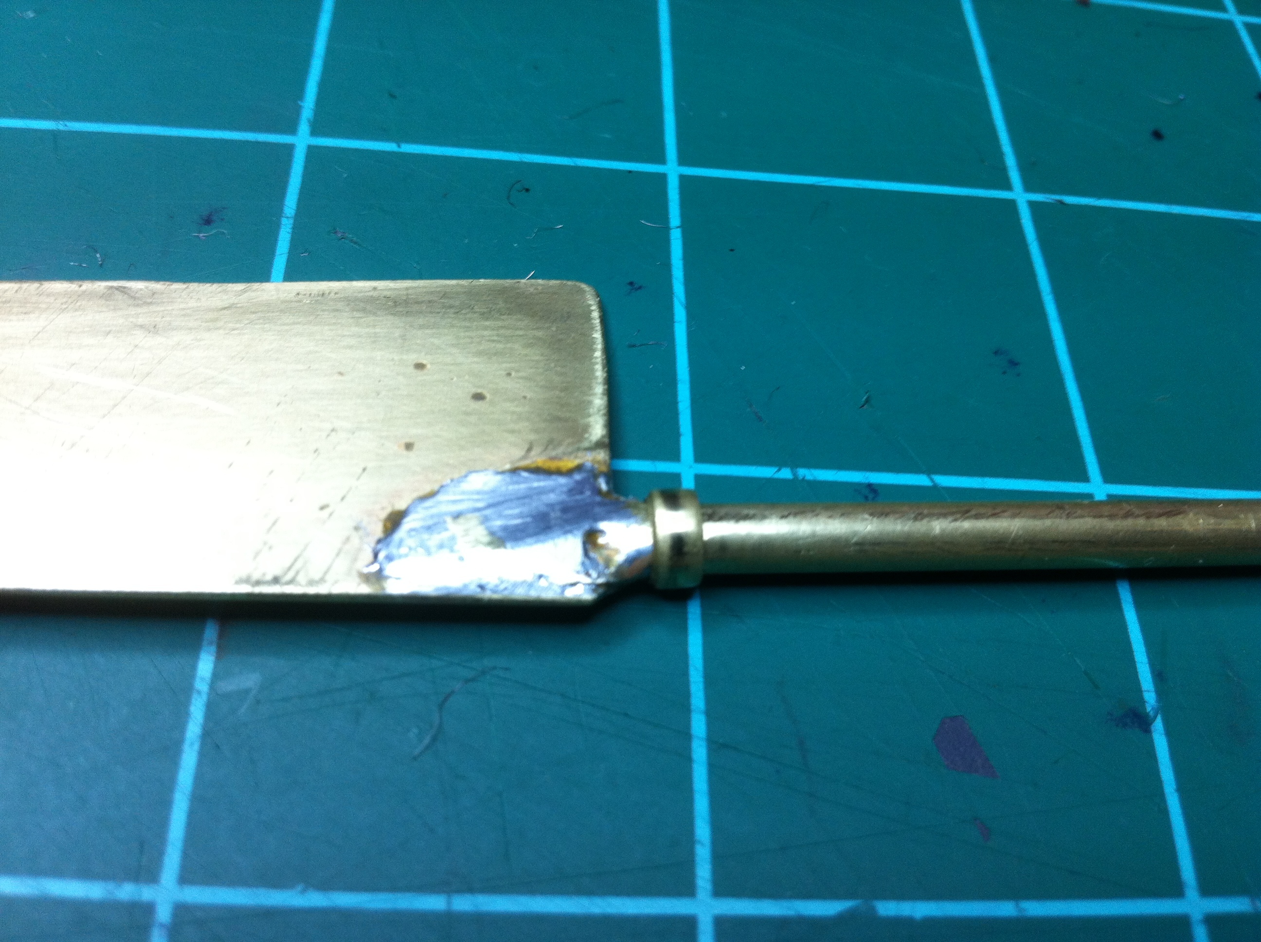
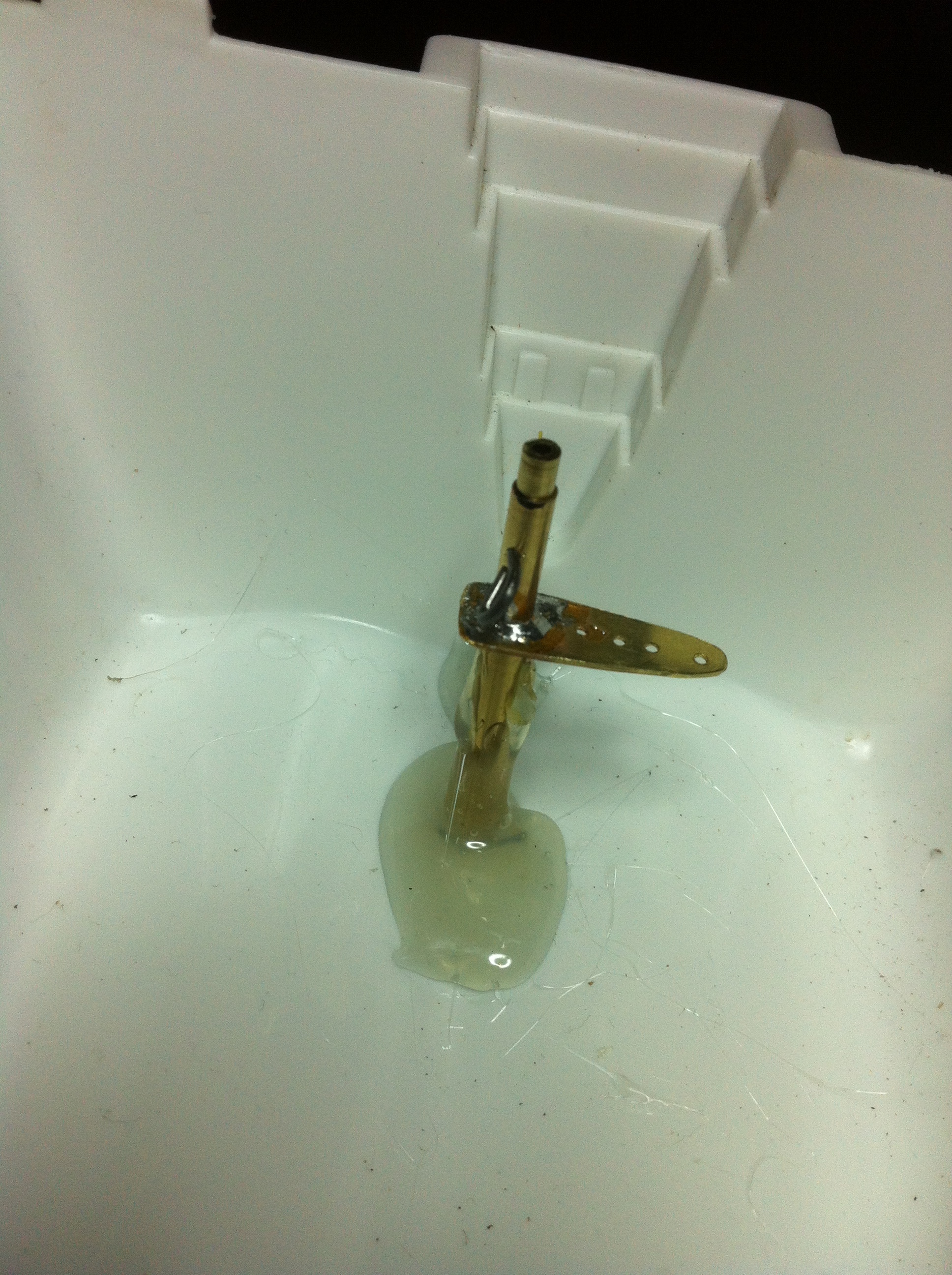
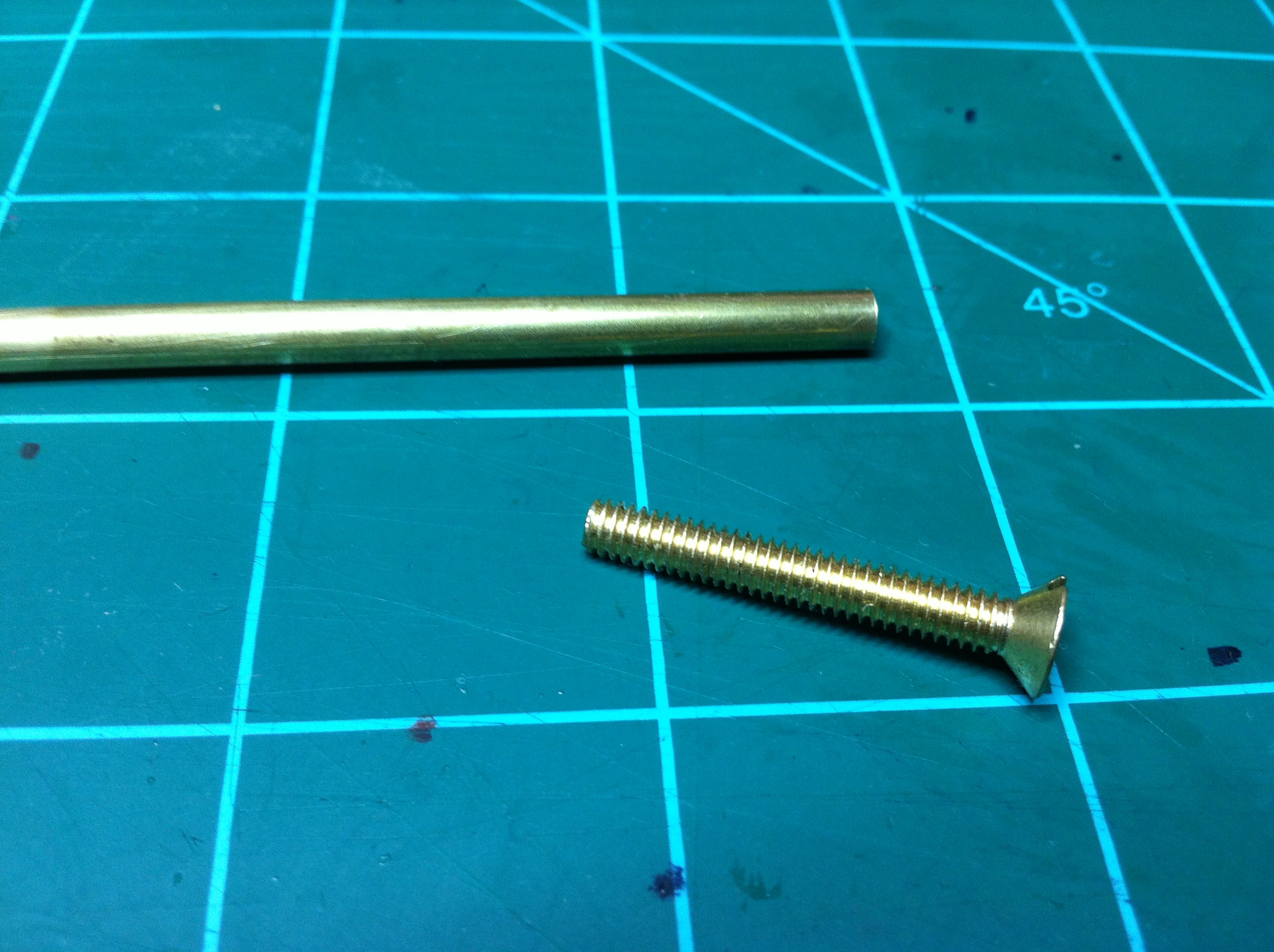
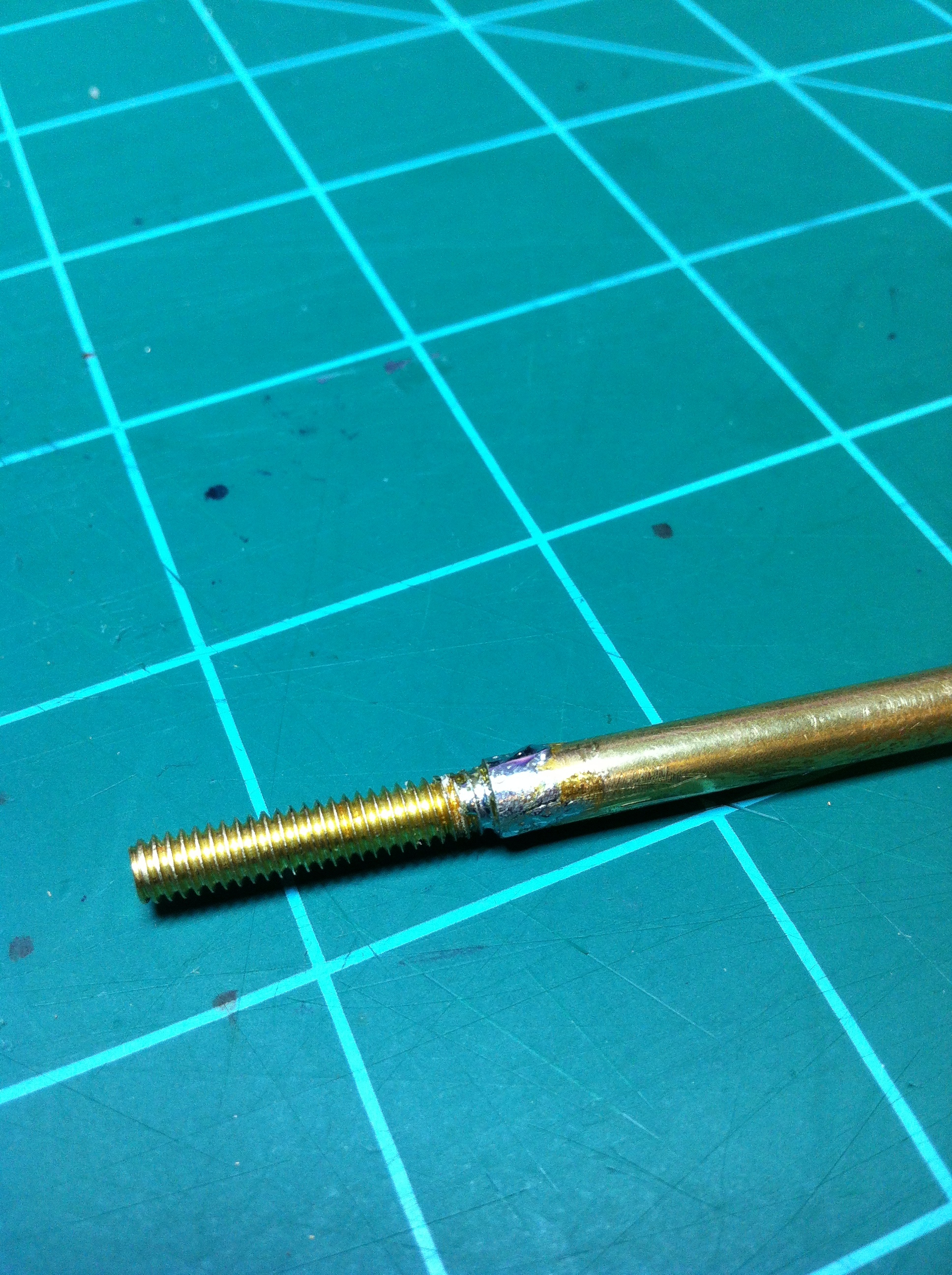
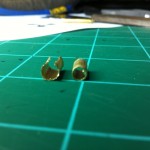
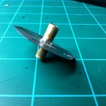
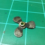
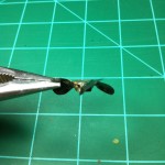
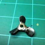
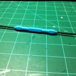
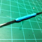
Like I said, the shaft will be made out of 3/16″ brass tubing. The shaft will be 12″ long because, well, that’s how long of a piece I bought. While at the hardware store I got a brass 1 1/2″ long 8/32 machine screw. To build the shaft I cut the head off of the machine screw, stuck the screw into the 3/16″ tube about 1/4″ – 1/2″, and then I soldered it. To mount the prop I will put a nut on the 8/32, followed by the prop, and then another nut. Since I was going to use the gas line that was on my desk for another project, I had to buy some at the hardware store. I looked around for some 1/8″ fuel line at this particular hardware store so I bought some 1/8″ vacuum tube. It will work just as good as fuel line would, I’m sure.
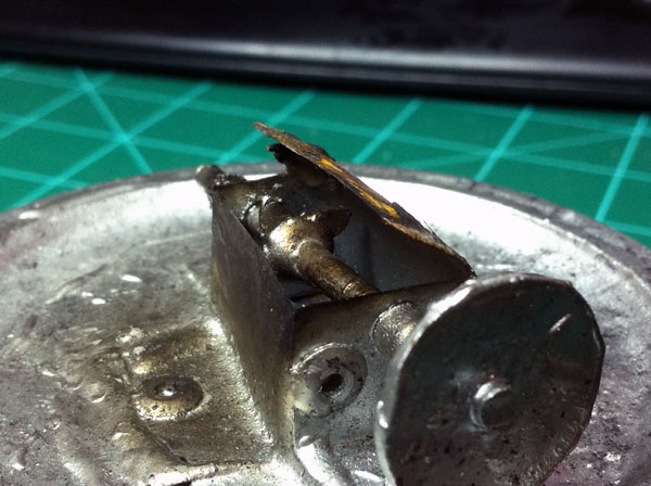
Stuffing Tube
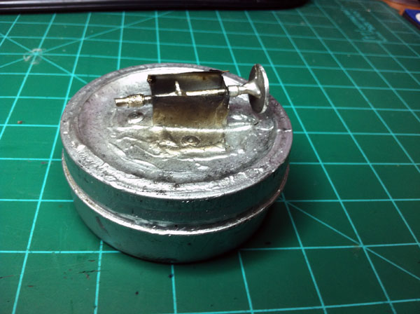
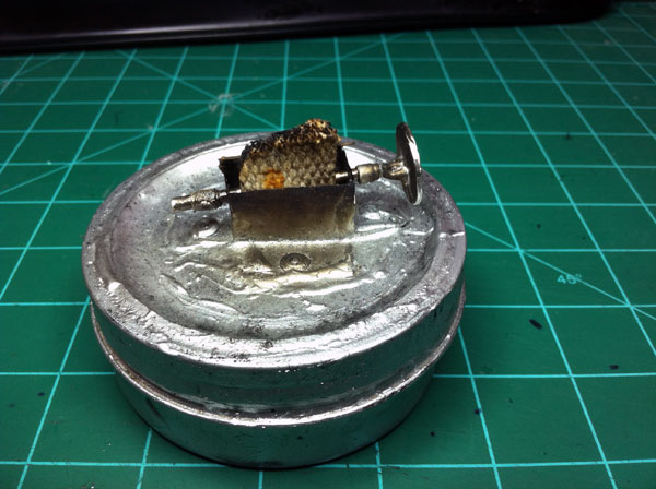
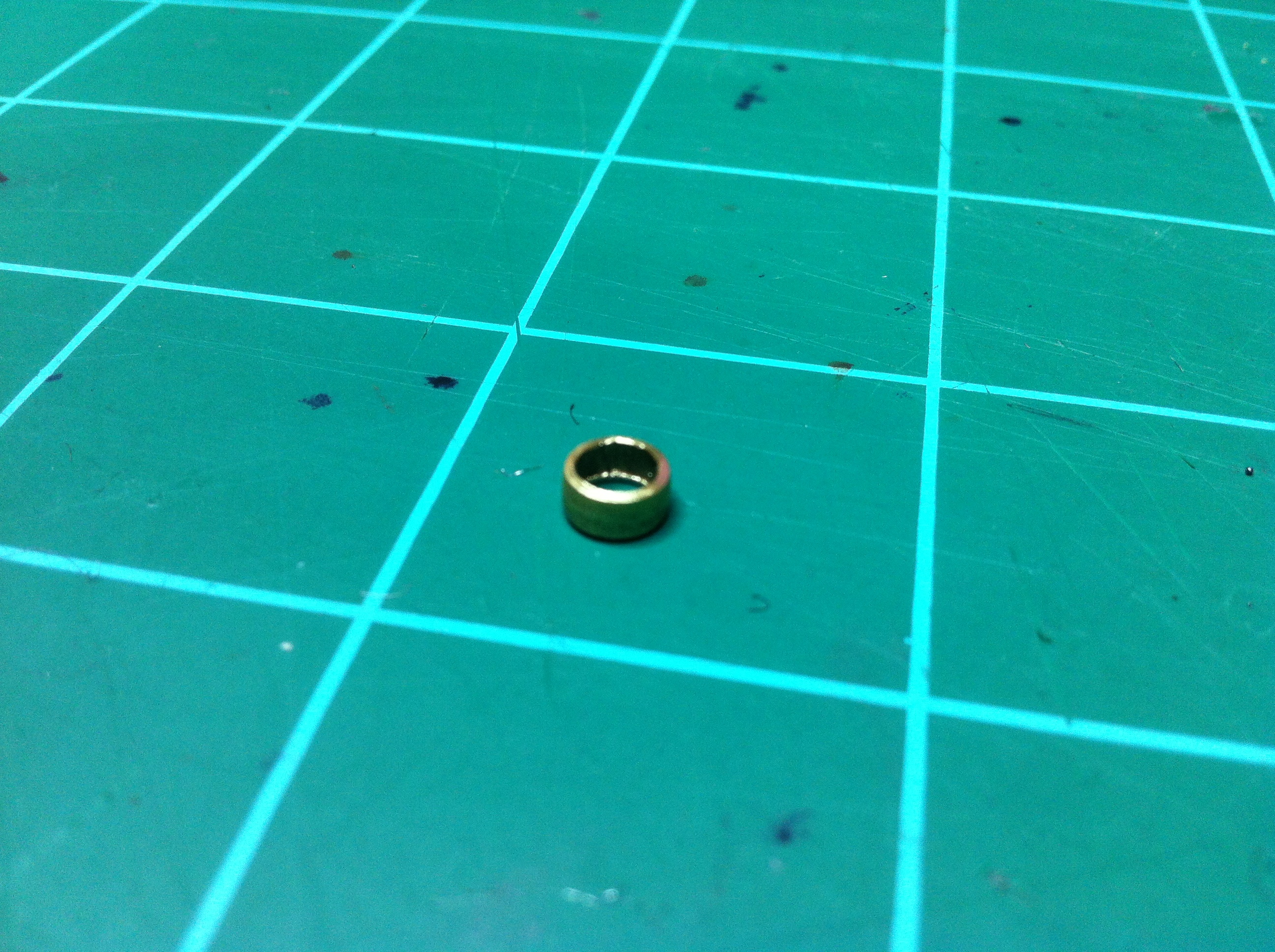
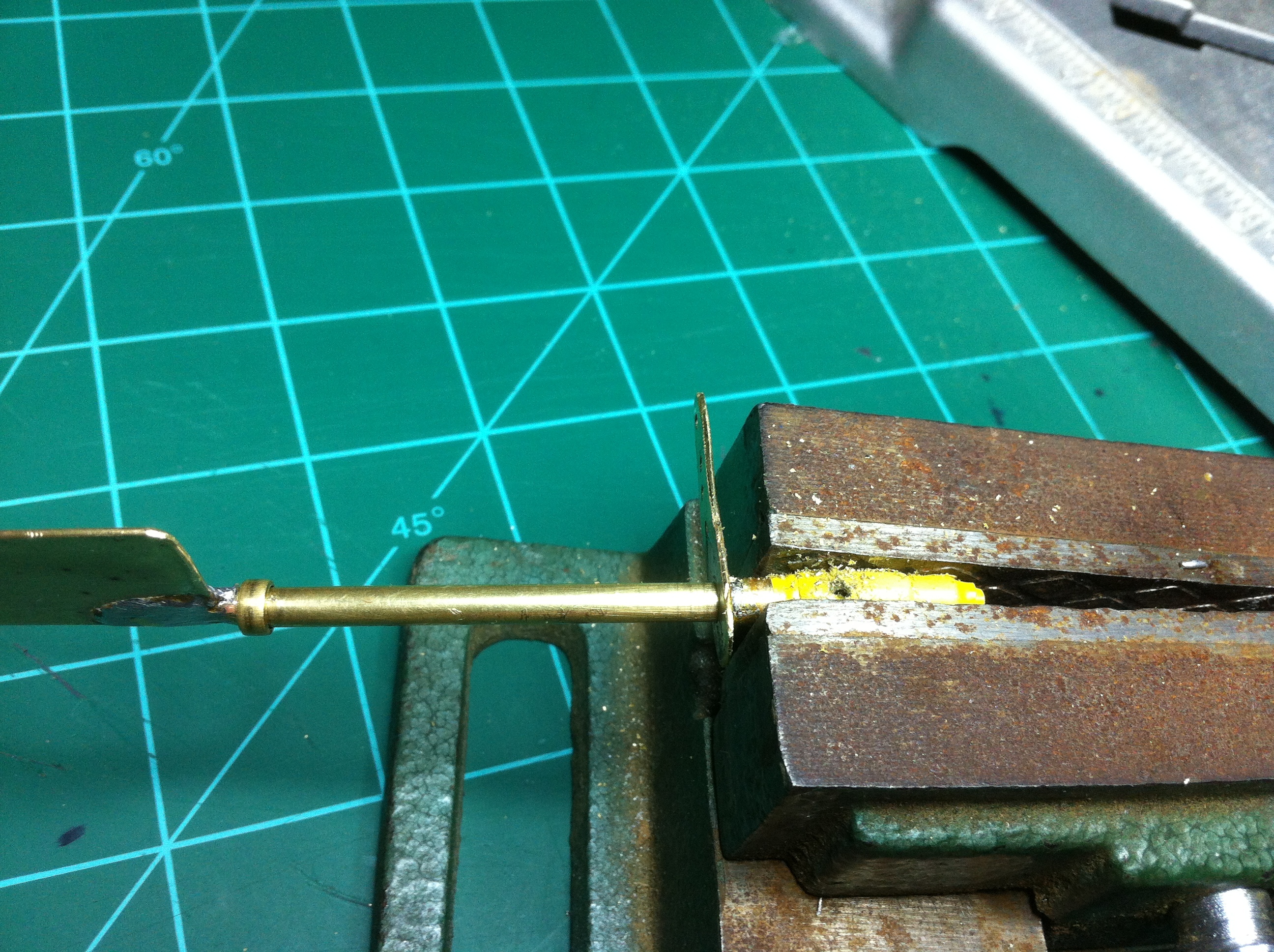
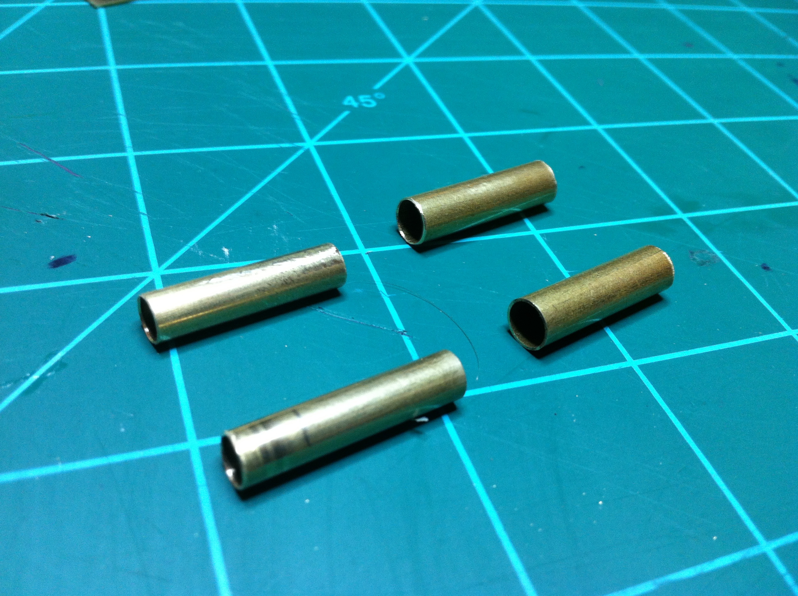
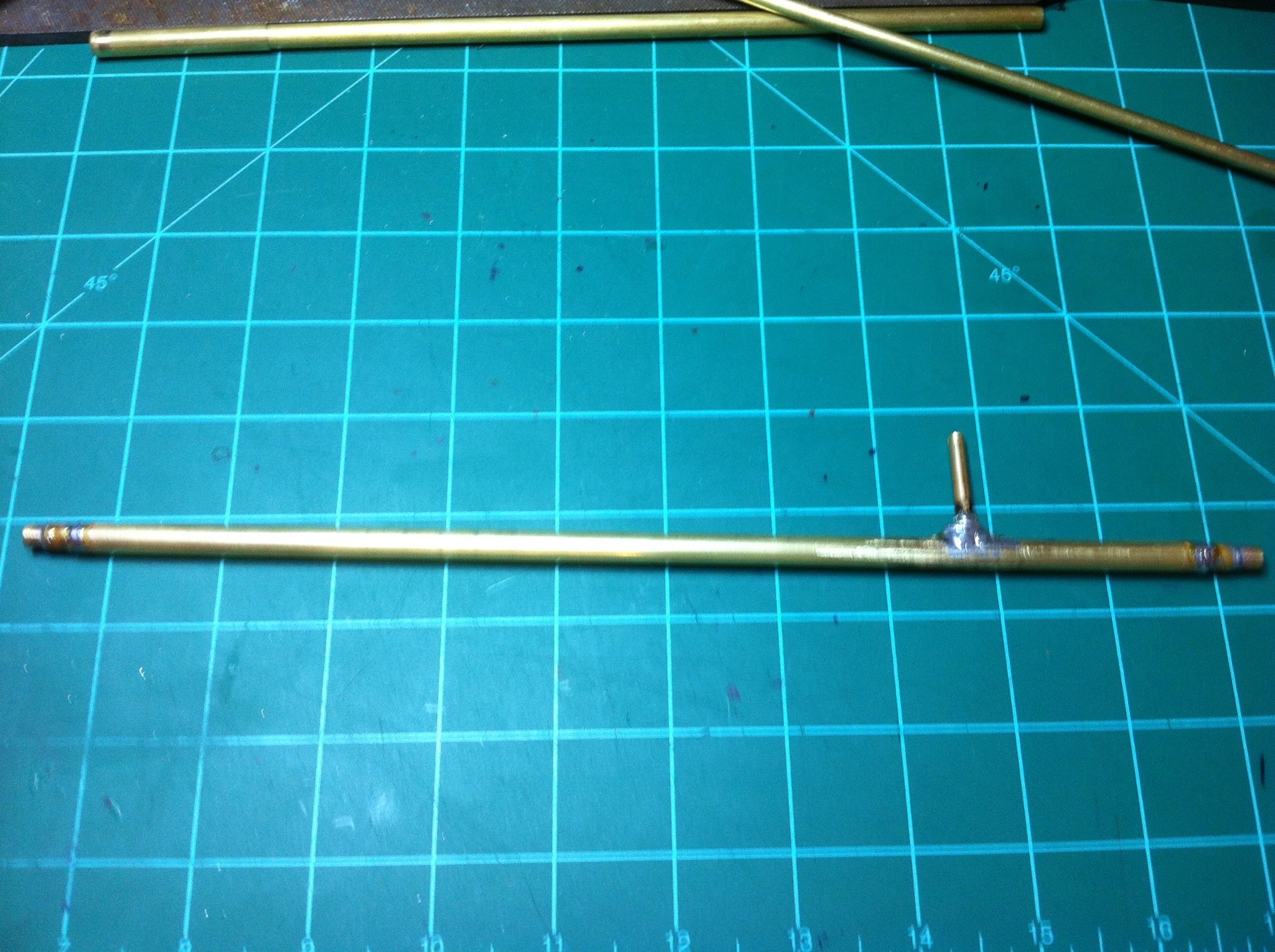
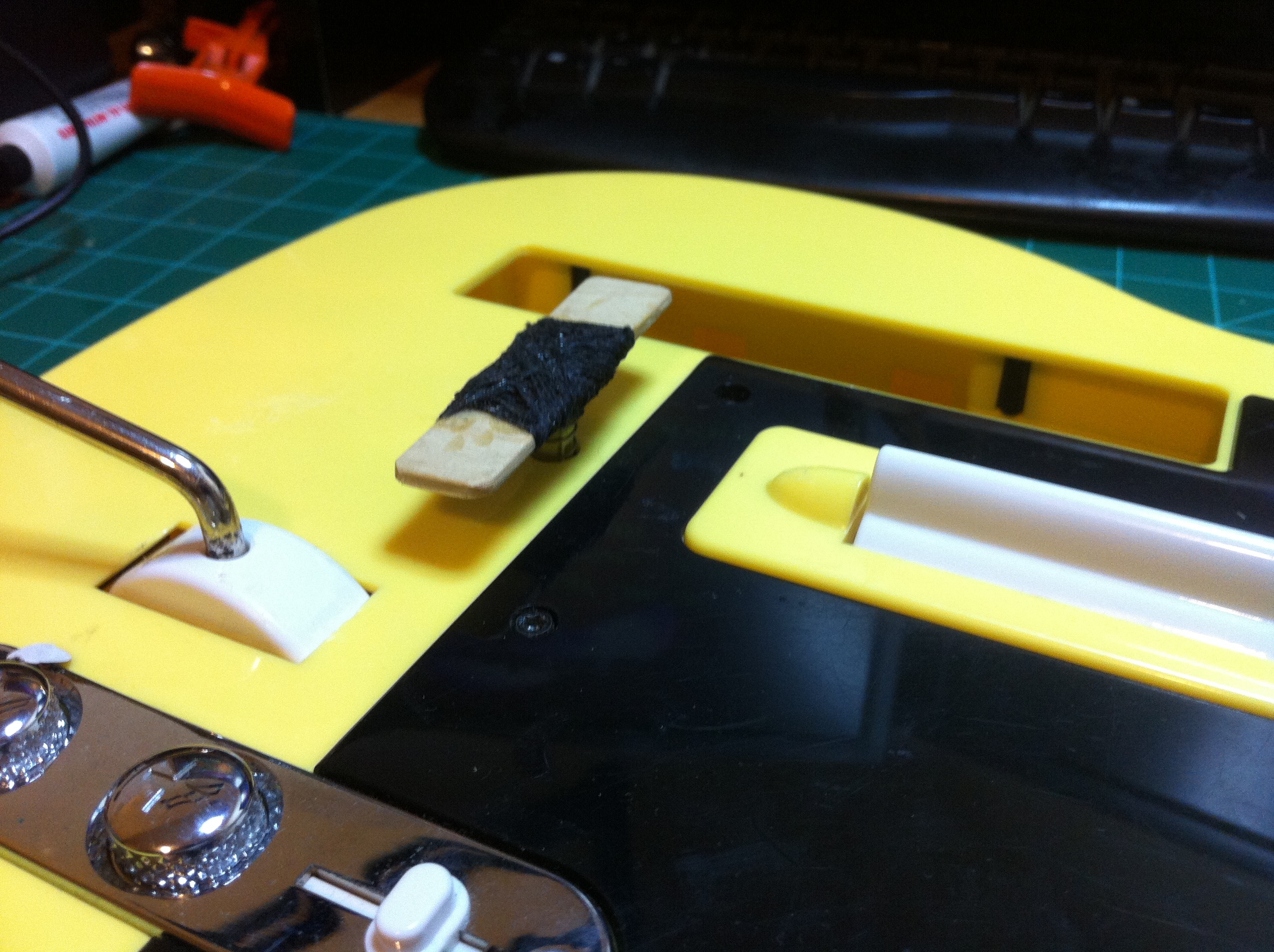
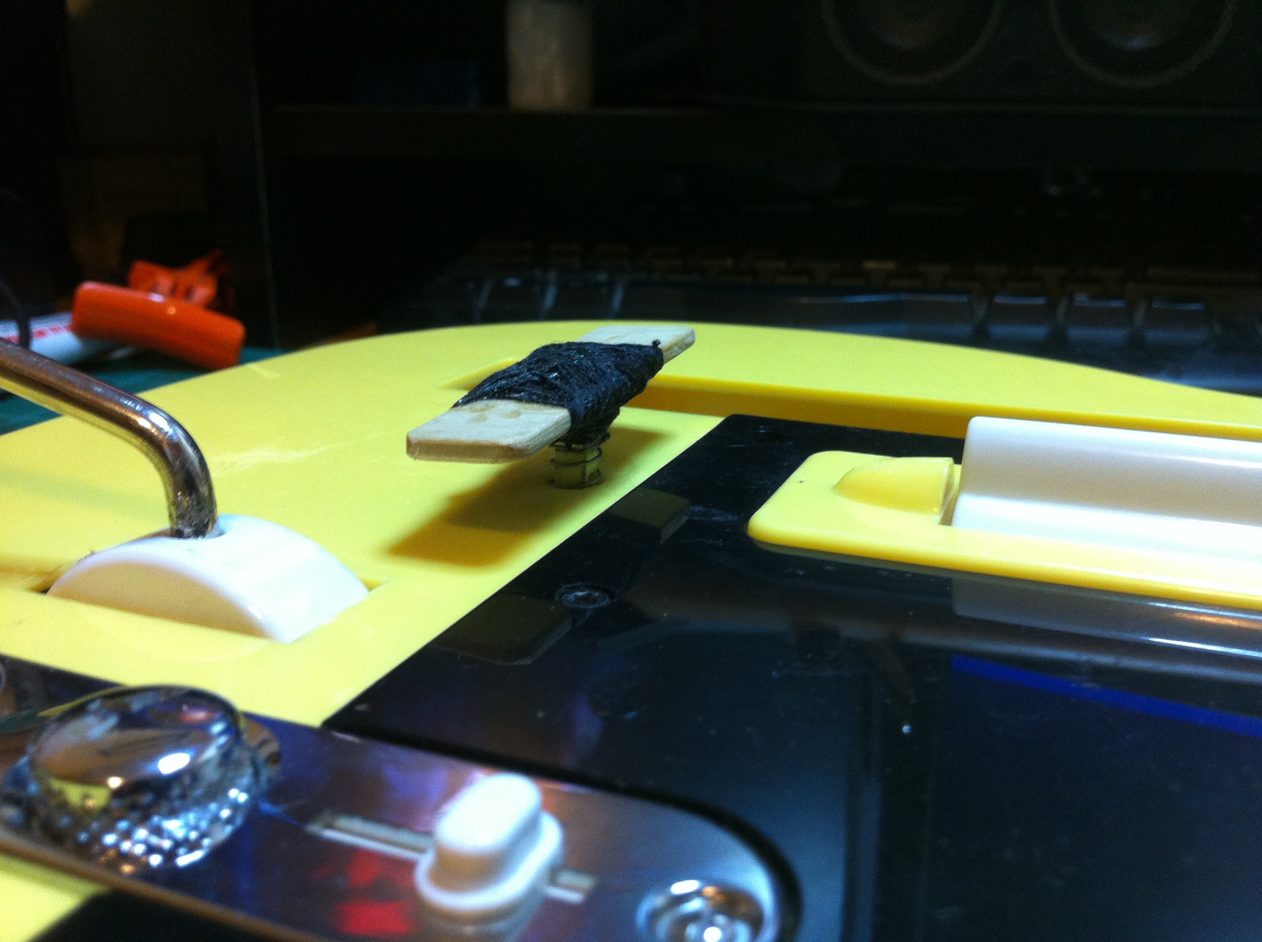
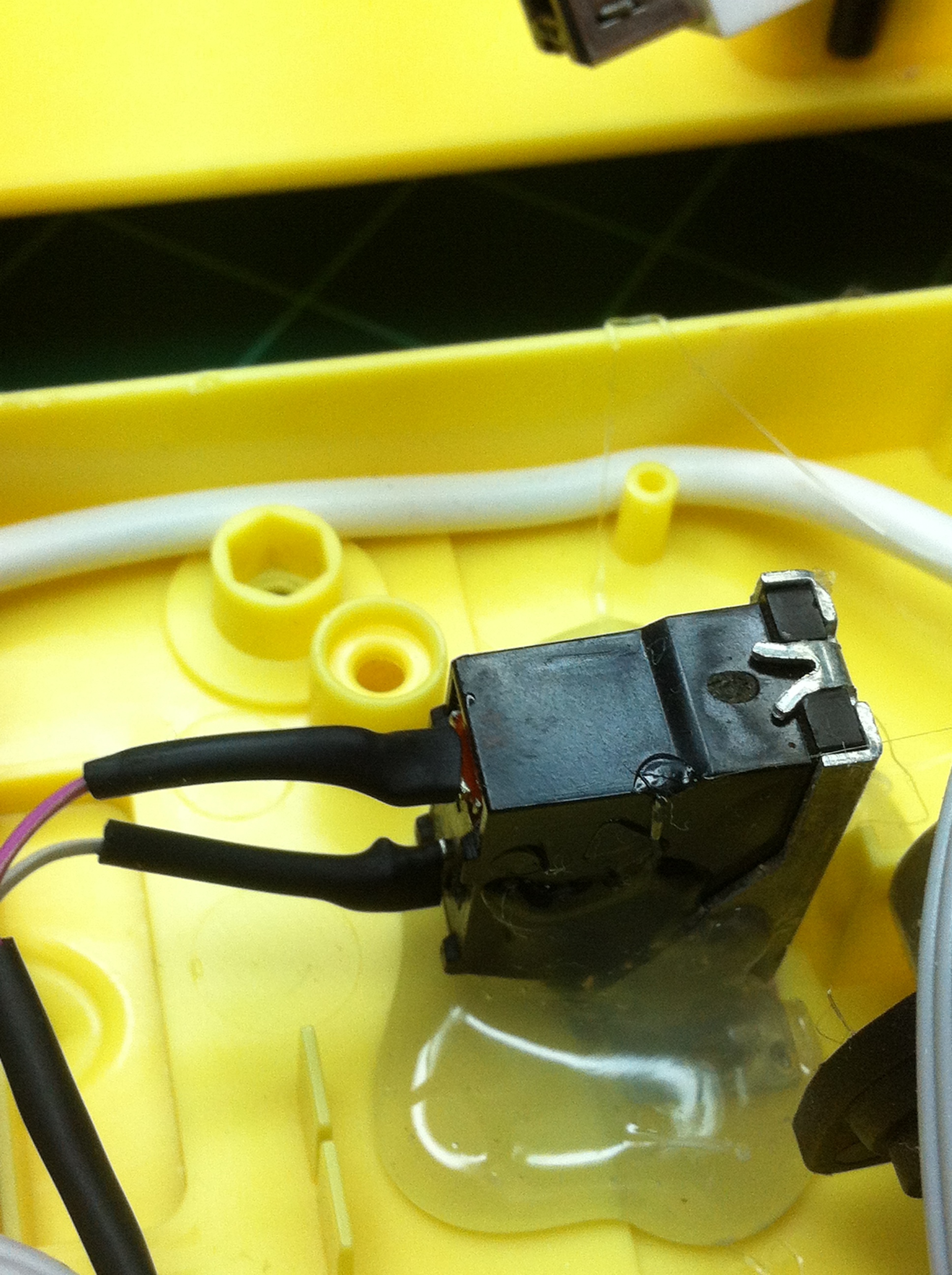
The stuffing tube is a tube that the shaft will spin inside of. The stuffing tube will have grease/oil in it. The stuffing tube will run from the inside of the hull to the outside, but the grease inside will keep water from getting into the hull via the tube. I started building the stuffing tube by taking the tube that slid over my 3/16″ shaft perfectly and cut two 1″ pieces of it. I then took the next larger size of tubing and again I cut two 1″ pieces. I then took the smaller sized 1″pieces and stuck them inside of the larger sized 1″pieces and soldered them together. I soldered the tubes where the smaller sized pieces stuck out of the larger sized by 1/4″. At this point I had made the two end bushings of the stuffing tube. Then I laid my shaft on the desk and beside it I laid my two stuffing tube bushings I made next to the shaft where they will go. I then got the largest tubing I bought (the one that the two bushings will slide snugly into) and laid that next to my shaft and bushings. I then marked and cut the large tubing to the right length. At this point I was ready to solder in the bushings to the ends of this tube, but I then started thinking. . .
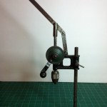
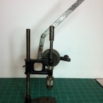
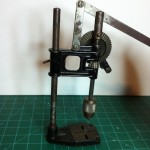
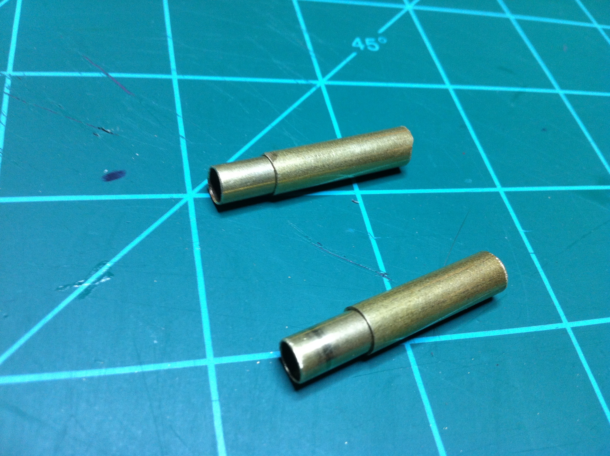
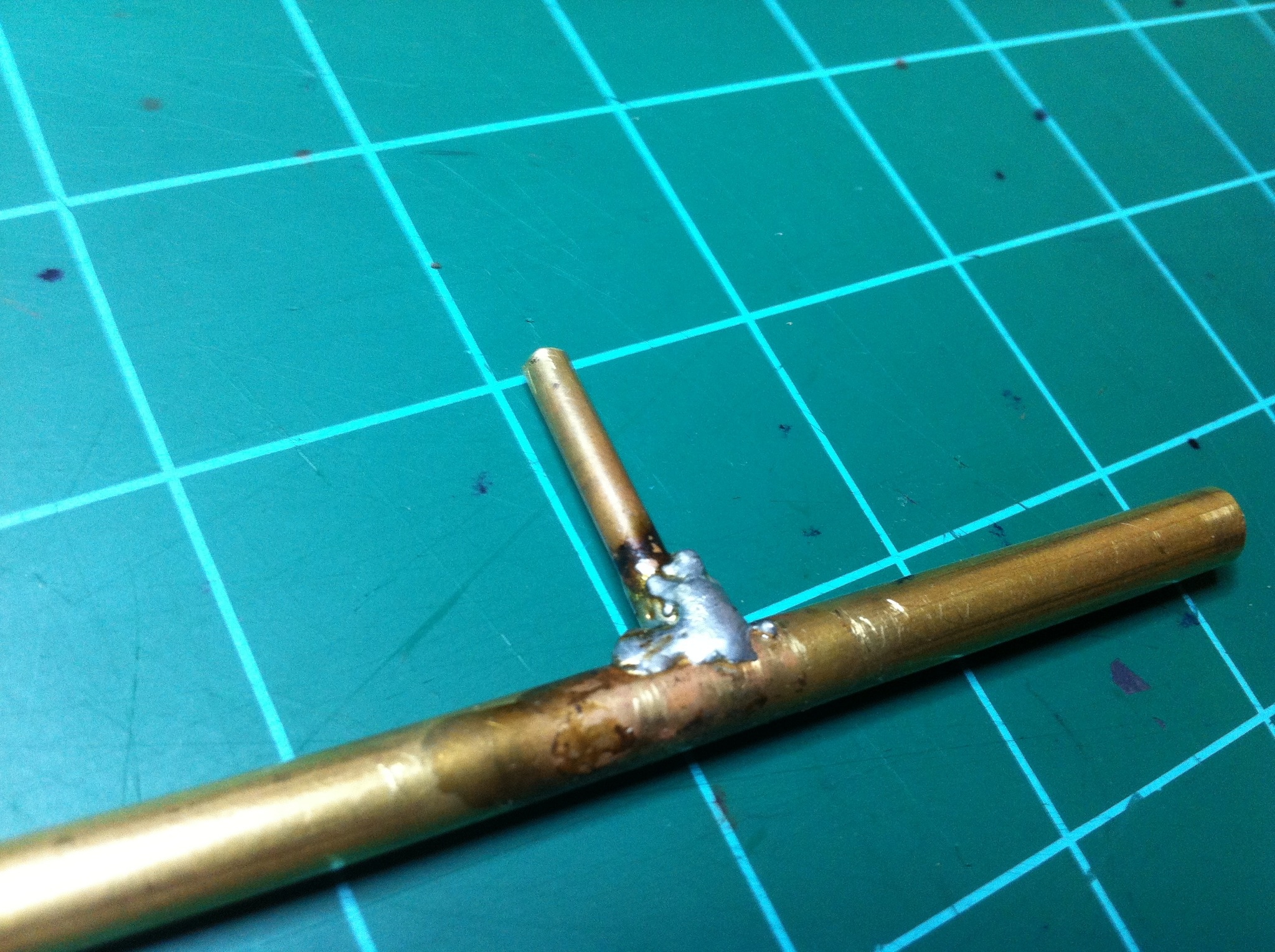
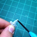
I thought, “How am I going to get the grease or oil into this stuffing tube after the boat is built. Sure I could stuff some grease in there now, but when I put the shaft in it will push some of it out and be a mess. Also if I put grease in now there will be no way to get a good solder joint on these bushings.” I decided then to solder a lubrication tube onto my soon-to-be stuffing tube. Using my Dremel drill press, I drilled an 1/8″ hole into the side of the tube about 2″ from one end. I then soldered a 1″ piece of 1/8″ IO brass tubing perpendicular to the large tube at this hole. This tube will allow me to use a syringe to pump some grease or oil into the stuffing tube. Now back to soldering the bushings. . .
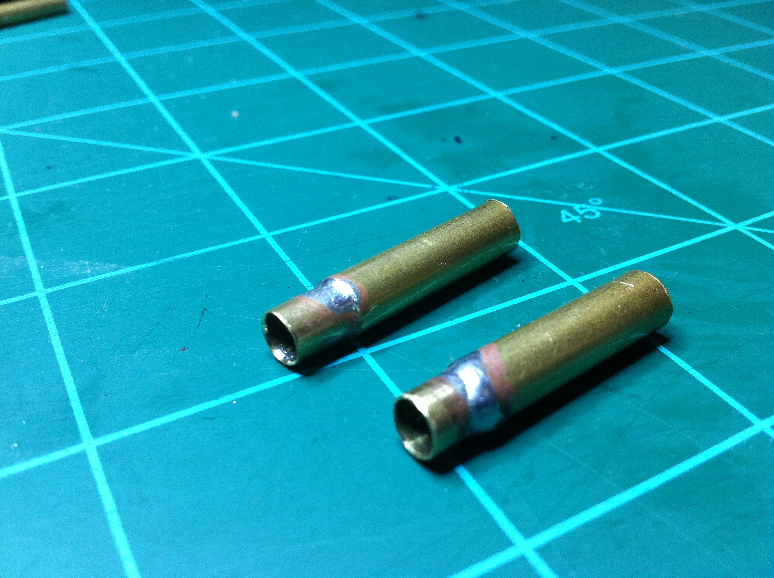
Okay, so I stuck the bushings into either end of the large tube with the bushings sticking out 1/2″ past the end of the large tube on both ends. Then I soldered the bushings into place. The stuffing tube is now complete.

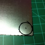
I will show how I made the rudder assembly next week . . .


Posted in Boats Tagged aqua, back, backroom, Boat, brass, build, c, control, d, dc, degree, diy, do, drive, grease, home, homemade, hydro, i, it, made, miniature, motor, oil, pack, packing, pitch, power, prop, propel, propeller, r, RC, remote, room, self, shaft, stuff, stuffing, train, tube, water, work, workdesk, y, your, yourself 1 Comment

RC Boat Propeller

As I was sitting bored at my desk surfing the web on RC boats, in particular homemade RC boats, I stumbled across a how-to on making your own brass propellers. When I have fooled around with making RC boats in the past, I’ve always had trouble when it came to making props. I once made a prop out of clay and have also used a prop that goes on the tail-rotor of a little Air Hogz heli, as you can imagine, neither one of these worked very well. When I saw this how-to, and saw how simple it was, I started scrounging up parts . . .

I found a small brass tube about 3/16″ diameter and it was about 3-4″ long. I knew that I didn’t have any brass sheet like the tutorial called for, but I did have a Dollar Tree cookie sheet I bought a few days before for the metal. Although I didn’t have the exact parts that the how-to called for, I knew I could build a prop with what I had laying around.

The first thing I did was cut a 3/4″ piece off of the brass tube, then I cut two 3/8″ long pieces. The 3/4″ piece will be the part that the prop will be built on, and eventually be the hub of the prop. The two 3/8″ pieces will be cut lengthwise and spread open a bit to slide over the 3/4″ piece. At this point I got some tin snips and cut off the walls of my cookie tray. I wanted a flat pice of sheet metal to work with. After I had the sides removed from the tray, I printed off the picture of propellers that the writer of the tutorial attached. I cut out the circle that encompassed the prop configuration that was colored in red. I then traced around the circle I just cut out onto the metal and then loosely cut that metal circle out. I drilled a hole in the center of the metal disk the same size as the diameter of my brass tube. I then slid the metal disk onto the 3/4″ long piece of brass tubing. After flaring out the two pieces of tubing that were 3/8″long, I slid them onto the 3/4″ piece of tube with the metal disk sandwiched in between. I then soldered all of this together. After carefully cutting out the center of the prop picture I had I used a glue-stick to stick the prop picture to the metal disk. I then cut out the propeller disk using tin snips as best I could. To clean up the edges of the prop I used a sandpaper disk and my Dremel. At this point the shaping of the prop was done, I now just needed to add some curve to the blades themselves and add some pitch to the prop.

I just eyeballed the curve of each blade. When the looked about right, I moved on. Same thing with the pitch, I just did what felt right and ran with it. I have never fooled with real RC boats before or anything, but I just made my best guess on the pitch of the prop.

While setting the pitch of the prop, my solder joint broke so I went and really gobbed on the solder. I don’t think it should break anytime soon.

I was very surprised how easy it was to make my own prop, but the real question is: does it work? I think it will work fine for me. When I spun it with a small brushed DC motor, it actually produced wind. I will keep ya’ll informed on how well it does. My only problem is, now I need to build a boat . . . .

Prop Pictures . . .


Posted in Boats Tagged aqua, back, backroom, Boat, brass, c, control, d, dc, degree, diy, do, drive, home, homemade, hydro, i, it, made, miniature, motor, pack, packing, pitch, power, prop, propel, propeller, r, RC, remote, room, self, shaft, stuff, stuffing, train, tube, water, work, workdesk, y, your, yourself

Cool Tools: Circuit Board Reamer

This is a new ‘segment’ I’m going to have on my blog. For now I will call it “Cool Tools” (unless I come up with a better name). It will just be where I tell about a tool that I find to be very handy, interesting, or just plain awesome. I don’t know how frequent this type of post will come up, but I guess it will be just when I find a tool that is worthy of being accepted into the Backroom Workdesk’s prestigious Cool Tool’s segment (Lol).

This is a new ‘segment’ I think I’m going to have on my blog. For now I will call it “Cool Tools” (unless I come up with a better name). It will just be where I tell about a tool that I find to be very handy, interesting, or just plain awesome. I don’t know how frequent this type of post will come up, but I guess it will be just when I find a tool that is worthy of being accepted into the Backroom Workdesk’s prestigious Cool Tool’s segment (Lol).

So the first tool I’m going to talk about is the Harbor Freight Circuit Board Reamer. The reason I have decided to write about this tool is because I have found it to be extremely handy to keep on my desk. I have never used it for circuit boards (and probably never will) but I have used it many times for various things. The main thing I use it for is to ream out the holes on servo horns to accept bigger wires.

This tool has two ends – one is square and one is round. They both come to a sharp point. I normally use the square end because it ‘cuts’ better, but I have used the round end a few times.

So you might be thinking to yourself, “Big deal. It’s pretty much just an awl.” Well, yeah it kinda is. But I’d highly recommend you pick one up and just keep it on your workdesk because you will quickly find many tasks that his tool is great for. For $1.99 you can’t beat it!


Posted in Cool Tools Tagged awesome, awl, blue, board, c, circuit, control, cool, frieght, handy, harbor, horn, interesting, poke, pokey, r, RC, reamer, servo, surface, tool

DIY Guitar Hero Star Power Button

The other day I played Guitar Hero for the first time in months (yes, I still have mad skills. haha). As I was playing I found it difficult to activate the star power. I know that the newer Guitar Hero brand guitars actually have a button that activates star power where the saddle would be on a real guitar. I only have the cheaper 3rd-party brand guitars and they do not have a button like this. I have to reach down and hit the ‘minus’ button to activate star power which makes it very easy to mess-up and lose my multiplier/streak. As I was playing I realized it couldn’t be too difficult to add my own button, so I opened up the guitar and began working. . .

The first thing I did was hold the guitar like I was playing and tried to find the best position for me to put in a button. Then I marked that place with a sharpie — Tip: I placed a piece of painters tape in the general area of where I was going to place the button, that way when the project was completed I could take off the tape and there would be no sharpie on the guitar itself. — After I had the button location marked, I opened up the guitar and started looking how to mount the button. The switch I decided on using was a switch I had saved from an old, junker computer. It seemed to be the perfect button because it had a spring on it that pushed the button back to the same position every time,  it was a momentary switch, and because it had a very long plastic ‘neck’ on it for mounting a ‘bar’.  As I mentioned in the last sentence, I planned on adding a wooden bar to the top of the switch to make it easier to hit while playing the guitar.   After I opened the guitar and made sure that the position I wanted to place my switch at was okay, (I was looking to see if there was a circuit board or other device in the guitar that would prevent me from placing my switch where I wanted) I drilled a hole (from the outside of the guitar) where the button was going to stick out at.

At this point it was time for me to find out the electrical side of the operation. Using the continuity function on my multi-meter, I found out which two traces made a complete circuit when the ‘minus’ button on the guitar was pressed. I then used some ribbon cable I robbed from the same junker computer I got my switch from and soldered it to one pole of my switch and I soldered the end of the wire to the end of one of the traces on the ‘minus’ button’s PCB. Then I did the same with another wire, but I soldered that one to the other pole of my switch and to the other trace on the PCB.  At this point I tested the setup with my multimeter to make sure my newly added switch closed the circuit. I then started up the guitar hero game and tested to make sure my switch activated starpower. I did these tests before mounting the switch and closing up the guitar because it would be a real pain in the neck to have to do all of this again.

Once everything was tested and working properly, I then could move onto the mechanical side of this project – mounting the switch. To mount the switch I used my favorite adhesive, hot glue! I stuck the switch through the hole I drilled previously and once I had it positioned to my liking, I really gobbed on the hot glue. Then it was time to add a bar to the top of the switch to make it way easier to hit while playing. I cut a piece of 1/8″ plywood ~ .75″ x 2.5″ and used thread and superglue (a lot of it) to firmly mount the plywood to the little stob on the switch.

I closed up the guitar and did a final test and, believe it or not, it worked! I could play a song and just bump the star power bar with my wrist and star power was activated. It doesn’t look too pretty, but it can make the difference from winning or losing on a Guitar Hero song!


Posted in Miscellaneous Tagged activate, bar, build, button, control, controller, custon, d, diy, game, guitar, guitarhero, hero, i, legends, mod, modded, music, of, own, play, power, rock, star, tour, toy, video, wii, world, y, your
  • « Older Entries
  • 1
  • 2
  • 3
  • …
  • 6
  • Newer Entries »

Proudly powered by WordPress | WordPress Theme Custom Community 2 developed by ThemeKraft